


1-29
Cisco ONS 15454 Installation and Operations Guide
November 2001
Chapter 1 Hardware Installation
Power and Ground Installation
Warning
Connect the ONS 15454 only to a DC power source that complies with the safety extra-low voltage
(SELV) requirements in IEC 60950-based safety standards.
Warning
The ONS 15454 relies on the protective devices in the building installation to protect against short
circuit, overcurrent, and grounding faults. Ensure that the protective devices are properly rated to
protect the system, and that they comply with national and local codes.
Warning
A readily accessible two-poled disconnect device must be incorporated in the fixed wiring.
Cisco recommends the following wiring conventions, but customer conventions prevail:
• Red wire for battery connections (-48V DC)
• Black wire for battery return connections (0V DC)
The ONS 15454 has redundant -48V DC #8 power terminals on the shelf assembly backplane. The
terminals are labeled BAT1, RET1, BAT2, and RET2 and are located on the lower section of the
backplane behind a clear plastic cover. See the “Lower Backplane Cover” section on page 1-15 for
information about accessing the power terminals.
To install redundant power feeds, use four power cables and one ground cable. For a single power feed,
only two power cables (#10 AWG, copper conductor, 194°F [90°C]) and one ground cable (#6 AWG)
are required. Use a conductor with low impedance to ensure circuit overcurrent protection. However, the
conductor must have the capability to safely conduct any fault current that might be imposed.
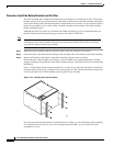
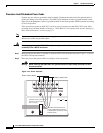
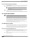
The existing ground post is a #10-32 bolt. The nut provided for a field connection is also a #10, with an
integral lock washer. The lug must be a dual-hole type and rated to accept the #6 AWG cable. Two posts
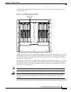
are provided on the Cisco ONS 15454 to accommodate the dual-hole lug. Figure 1-22 shows the location
of the ground posts.
Figure 1-22 Ground posts on the ONS 15454 backplane
For information about attaching ferrites to power cabling, see the “Ferrite Installation” section on
page 1-61.
Warning
When installing redundant power feeds, do not use aluminum conductors.
Warning
If you use redundant power leads to power the ONS 15454, disconnecting one lead will not remove
power from the node.
FRAME GROUND
61852