


7-27
Cisco ONS 15454 Installation and Operations Guide
November 2001
Chapter 7 Card Provisioning
Provisioning the Alarm Interface Controller
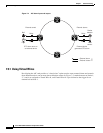
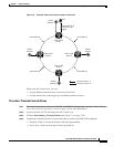
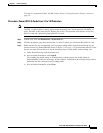
Figure 7-5 External alarms and controls using a virtual wire
When using AIC virtual wires, you can:
• Assign different external devices to the same virtual wire.
• Assign virtual wires as the trigger type for different external controls.
Procedure: Provision External Alarms
Step 1 Wire the external-device relays to the ENVIR ALARMS IN backplane pins. See the “Alarm, Timing,
LAN, and Craft Pin Connections” section on page 1-32 for more information.
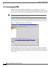
Step 2 Log into the node in CTC and display the AIC in card view.
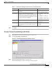
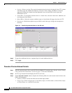
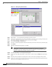
Step 3 Click the Provisioning > External Alarms tabs (Figure 7-6 on page 7-28).
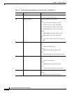
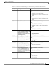
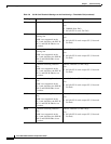
Step 4 Complete the following fields for each external device wired to the ONS 15454 backplane:
• Enabled—Click to activate the fields for the alarm input number.
• Alarm Type—Select an alarm type from the provided list.
ONS 15454
Node 1
Virtual Wire #1 is
external control
trigger
Virtual Wire #1
Smoke
detector
Bell
Smoke
detector
ONS 15454
Node 2
ONS 15454
Node 3
ONS 15454
Node 4
Virtual Wire #1
Virtual Wire #1 Virtual Wire #1
= External alarm
= External control
Smoke
detector
Smoke
detector
44743