


5-19
Cisco ONS 15454 Installation and Operations Guide
November 2001
Chapter 5 SONET Topologies
Bidirectional Line Switched Rings
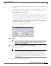
Step 2 Log into CTC and display the BLSR nodes in network view. Verify the following:
• All BLSR spans on the network map are green.
• On the Alarms tab, no critical or major alarms are present, nor any facility alarms, such as LOS,
LOF, AIS-L, SF, and SD. In a BLSR, these facility conditions may be reported as minor alarms.
• On the Conditions tab, no ring switches are active.
If trouble is indicated, for example, a major alarm exists, resolve the problem before proceeding.
Step 3 Install the OC-N cards in the ONS 15454 that you will add to the BLSR; use the “Install the BLSR Trunk
Cards” procedure on page 5-11. Ensure fiber cables are available to connect to the cards. Run test traffic
through the node to ensure the cards are functioning properly.
Step 4 Log into the new node and complete the BLSR setup.
• Provision the SONET DCC using the “Create the BLSR DCC Terminations” procedure on
page 5-13.
• Configure the BLSR timing using the “Set up ONS 15454 Timing” procedure on page 3-14.
• Enable the BLSR ports using the “Enable the BLSR Ports” procedure on page 5-13.
• Provision the BLSR using the “Provision the BLSR” procedure on page 5-14
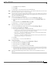
Step 5 Log into the node that will connect to the new node through its east port (Node 4 in the Figure 5-15
example).
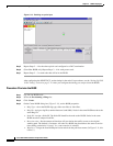
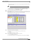
Step 6 Switch protection on the east port:
a. Click the Maintenance > Ring tabs.
b. From the East Switch list, choose FORCE RING. Click Apply.
Performing a FORCE switch generates a manual switch request on an equipment (MANUAL-REQ)
alarm. This is normal.
Caution Traffic is unprotected during a protection switch.
Step 7 Log into the node that will connect to the new node through its west port (Node 1 in the Figure 5-15
example).
Step 8 Switch protection on the west port:
a. Click the Maintenance > Ring tabs.
b. From the West Switch list, choose FORCE RING. Click Apply.
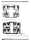
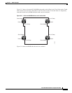
Step 9 Following the diagram that you created in Step 1, remove the fiber connections from the two nodes that
will connect directly to the new node.
a. Remove the east fiber from the node that will connect to the west port of the new node. In the
Figure 5-15 example, this is Node 4/Slot 12.
b. Remove the west fiber from the node that will connect to the east port of the new node. In the
Figure 5-15 example, this is Node 1/Slot 5.
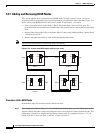
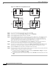
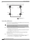
Step 10 Replace the removed fibers with fibers that are connected to the new node. Connect the west port to the
east port and the east port to the west port. Figure 5-16 shows the BLSR in the Figure 5-15 example after
the node is connected.