


5-21
Cisco ONS 15454 Installation and Operations Guide
November 2001
Chapter 5 SONET Topologies
Bidirectional Line Switched Rings
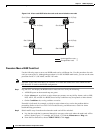
Procedure: Remove a BLSR Node
Caution The following procedure minimizes traffic outages during node deletions, but traffic will be lost
when you delete and recreate circuits that passed through the deleted node.
Step 1 Before you start this procedure, make sure you know the following:
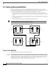
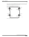
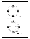
• Which node is connected through its east port to the node that will be deleted. For example if you
are deleting Node 1 in Figure 5-16, Node 3 is the node connected through its east port to Node 1.
• Which node is connected through its west port to the node that will be deleted. In Figure 5-16, Node
2 is connected to Node 1 through its west port.
Step 2 Log into a node on the same BLSR as the node you will remove. (Do not log into the node that you will
remove.)
Step 3 Display the BLSR nodes in network view and verify the following:
• All BLSR spans on the network map are green.
• No critical or major alarms (LOF, LOS, ASP, ASL) are displayed on the Alarms tab.
• On the Conditions tab, no ring switches are active.
If trouble is indicated, for example, a critical or major alarm exists, resolve the problem before
proceeding.
Step 4 Display the node that you will remove in node view.
Step 5 Delete all the circuits that originate or terminate in that node. (If a circuit has multiple drops, delete only
the drops that terminate on the node you want to delete.)
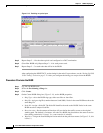
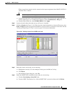
a. Click the Circuits tab. The circuits that use this node are displayed.
b. Select circuits that originate or terminate on the node. Click Delete.
c. Click Yes when prompted.
d. If a multidrop circuit has drops at the node that will be removed, select the circuit, click Edit, and
remove the drops.
Step 6 Complete this step if circuits that were created using Cisco Transport Controller Release 2.x. pass
through the node that will be deleted (i.e., circuits are displayed on the Circuits tab).
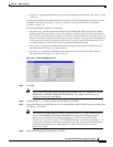
a. On the Circuits tab of the node that will be deleted, select a circuit and click Edit.
b. On the Edit Circuits window, check Show Detailed Map.
c. Verify that the circuits enter and exit the node on the same STS. For example, if a circuit enters on
s5/p1/S1 (Slot 5, Port 1, STS1), verify that it exits on STS1. If a circuit enters/exits on different
STSs, write down the name of the circuit. You will delete and recreate these circuits in Step e.
d. From the View menu select Go to Network View, then select the Circuits tab.
e. Delete and recreate each circuit recorded in Step c. To delete the circuit, select the circuit on the
Circuits window and click the Delete button. To create the circuit, go to the “Create an
Automatically Routed Circuit” procedure on page 6-2.
f. Repeat Steps a – e for each circuit displayed on the Circuits tab.