


1-22
Cisco ONS 15454 Installation and Operations Guide
November 2001
Chapter 1 Hardware Installation
EIA Installation
Procedure: Install a BNC, High-Density BNC, or SMB EIA
See the “Install the AMP Champ EIA” procedure on page 1-24 if you are using an AMP Champ EIA.
Step 1 To remove the lower backplane cover, loosen the five screws that secure it to the ONS 15454 and pull it
away from the shelf assembly.
Step 2 Remove the EIA card from the packaging. Line up the connectors on the card with the mating connectors
on the backplane. Gently push the card until both sets of connectors fit together snugly.
Step 3 Place the metal EIA cover panel over the card.
Step 4 Insert and tighten the nine perimeter screws (P/N 48-0358) at 8-10 lbs to secure the cover panel to the
backplane.
Step 5 Insert and tighten the twelve (BNC and SMB) or nine (High-Density BNC) inner screws (P/N 48-0004)
at 8-10 lbs to secure the cover panel to the card and backplane.
Step 6 Replace the lower backplane cover, and insert and tighten the five screws to secure it.
If you are using SMB EIAs to make DS-1 connections, you need the DS-1 electrical interface adapter,
commonly referred to as a balun (P/N 15454-WW-14=).
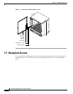
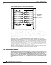
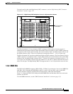
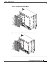
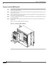
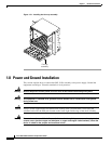
Figure 1-16 shows a BNC EIA installation. Figure 1-17 shows High-Density BNC EIA installation.
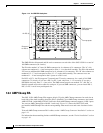
Figure 1-18 shows an SMB EIA installation.
Figure 1-16 Installing the BNC EIA
43764