


5-49
Cisco ONS 15454 Installation and Operations Guide
November 2001
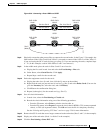
Chapter 5 SONET Topologies
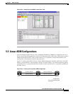
Linear ADM Configurations
Step 9 In the middle node, place the cards in Slots 5 and 13 out of service:
a. Display the first card in card view, then select the Provisioning > Line tabs.
b. Under Status, select Out of Service. Click Apply.
c. Repeat Steps a and b for the second card.
Step 10 Delete the equipment records for the cards:
a. From the View menu, choose Node View.
b. Right-click the card you just took out of service (e.g. Slot 5) and select Delete Card. (You can also
go to the Inventory tab, select the card, and click Delete.)
c. Click Yes on the confirmation dialog box.
d. Repeat (a) through (c) for the second card (e.g. Slot 13).
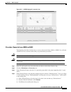
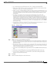
Step 11 Save all circuit information:
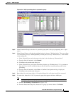
a. In node view, select the Provisioning > Circuits tab.
b. Record the circuit information using one of the following procedures:
–
From the File menu, select Print to print the circuits table, or,
–
From the File menu, select Export to export the circuit data in HTML, CSV (comma separated
values), or TSV (tab separated values). Click Ok and save the file in a temporary directory.
See the “Printing and Exporting CTC Data” section on page 2-26 for more information.
Step 12 Remove the OC-N cards that are no longer connected to the end nodes (Slots 5 and 13, in the example).
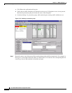
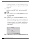
Step 13 Log into an end node. In node view, click the Provisioning > Sonet DCC tabs.
Step 14 In the SDCC Terminations section, click Create.
Step 15 Highlight the slot that is not already in the SDCC Terminations list (in this example, Port 1 of Slot 5
(OC-48) on Node 1.
Step 16 Click OK. (An EOC SDCC alarm will occur until the DCC is created on the other node; in the example,
Node 3/Slot 13.
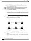
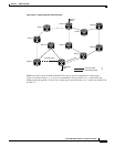
Step 17 Display the node on the opposite end (Node 3 in Figure 5-38) and repeat Steps 13 – 16.
Step 18 For circuits running on a BLSR protect STS (STSs 7 – 12 for an OC-12 BLSR, STSs 25 – 48 for an
OC-48 BLSR), delete and recreate the circuit:
a. Delete the first circuit.
b. Recreate the circuit on STSs 1 – 6 (for an OC-12 BLSR) or 1 – 24 (for an OC-48 BLSR) on the fiber
that served as the protect fiber in the linear ADM. During circuit creation, deselect “Route
Automatically” and “Fully Protected Path” on the Circuit Creation dialog box so you can manually
route the circuit on the appropriate STSs. See the “Create a Unidirectional Circuit with Multiple
Drops” procedure on page 6-8 for more information.
c. Repeat Steps (a) and (b) for each circuit residing on a BLSR protect STS.
Note Deleting circuits is traffic affecting.
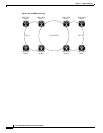
Step 19 Follow all procedures in the “Setting Up BLSRs” section on page 5-10 to configure the BLSR. The ring
should have an East/West logical connection. While it may not physically be possible to connect the
OC-N cards in an East/West pattern, it is strongly recommended. If the network ring that is already
passing traffic does not provide the opportunity to connect fiber in this manner, logical provisioning can
be performed to satisfy this requirement.