


6-15
Cisco ONS 15454 Installation and Operations Guide
November 2001
Chapter 6 Circuits and Tunnels
Cross-Connect Card Capacities
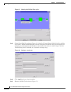
Step 8 On the circuit map, right-click the drop port for the circuit and select Edit Path Trace from the shortcut
menu.
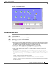
Step 9 On the Circuit Path Trace window (Figure 6-8) in the New Transmit String field (this field is available
only on DS-1, DS3E, and DS3XM cards), enter the string that you want the drop port to transmit. If the
field is left blank, the J1 transmits an empty string.
Step 10 If you will set Path Trace Mode to Manual in Step 11, enter the string that the drop port should expect
to receive in the New Expected String field. This string must match the New Transmit String entered for
the source port in Step 5. (When you click Apply in Step 12, this string becomes the Current Expected
String.)
Step 11 In the Path Trace Mode field, select one of the following options:
• Auto—Assumes the first string received from the source port is the baseline string. An alarm is
raised when a string that differs from the baseline is received.
• Manual—Uses the Current Expected String field as the baseline string. An alarm is raised when a
string that differs from the Current Expected String is received.
Step 12 Click Apply and then click Close.
Step 13 Display the Circuit Path Trace window for the source port from Step 5.
Step 14 If you will set the Path Trace Mode to Manual in Step 15, enter the string the source port should expect
to receive in the New Expected String field. This string must match the New Transmit String entered for
the source port in Step 9.
Step 15 In the Path Trace Mode field, select one of the following options:
• Auto—Assumes that the first string received from the drop port is the baseline string. An alarm is
raised when a string that differs from the baseline is received.
• Manual—Uses the Current Expected String field as the baseline string. An alarm is raised when a
string that differs from the Current Expected String is received.
Step 16 Click Apply and click Close.
After you set up the path trace, the received string is displayed in the Received box on the path trace
setup window (Figure 6-8). Click Switch Mode to toggle between ASCII and hexadecimal display.
Click the Reset button to reread values from the port. Click Default to return to the path trace default
settings (Path Trace Mode is set to Off and the New Transmit and New Expected Strings are null).
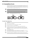
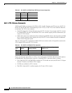
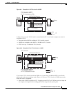
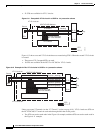
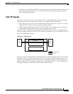
6.8 Cross-Connect Card Capacities
The ONS 15454 XC, XCVT, and XC10G cards perform port-to-port time-division multiplexing (TDM).
• XCs perform STS switching
• XCVTs and XC10Gs perform STS and VT1.5 switching
XCs and XCVTs have capacity to terminate 288 STSs, or 144 STS cross-connections (each STS
cross-connection uses two STS ports on the cross-connect card STS matrix). XC10Gs have capacity for
1152 STSs, or 576 STS cross-connections. Table 6-3 shows STS capacities for the XC, XCVT, and
XC10G cards.
Note The Cisco ONS 15454 Troubleshooting and Maintenance Guide contains detailed specifications of
the XC, XCVT, and XC10G cards.