


1-34
Cisco ONS 15454 Installation and Operations Guide
November 2001
Chapter 1 Hardware Installation
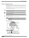
Alarm, Timing, LAN, and Craft Pin Connections
Note Refer to Telcordia SR-NWT-002224 for rules about provisioning timing references
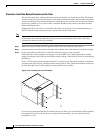
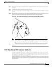
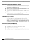
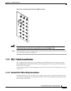
Procedure: Install Timing Wires on the Backplane
Step 1 Use #22 or #24 AWG wire.
Step 2 Wrap the clock wires on the appropriate wire-wrap pins according to local site practice.
Step 3 The BITS pin field (FG1) has a frame ground pin beneath it. Wrap the ground shield of the alarm cable
to the frame ground pin.
Note For more detailed information about timing, see the “Setting Up ONS 15454 Timing” section
on page 3-12.
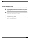
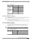
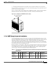
1.9.3 LAN Installation
Use the LAN pins on the ONS 15454 backplane to connect the ONS 15454 to a workstation or Ethernet
LAN, or to a LAN modem for remote access to the node. You can also use the LAN port on the TCC+
faceplate to connect a workstation or to connect the ONS 15454 to the network. Table 1-3 shows the
LAN pin assignments.
Before you can connect an ONS 15454 to other ONS 15454s or to a LAN, you must change the default
IP address that is shipped with each ONS 15454 (192.1.0.2). See the “Change IP Address, Default
Router, and Network Mask Using the LCD” procedure on page 3-4.
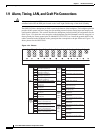
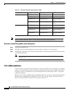
Table 1-2 External Timing Pin Assignments for BITS
External Device Contact Tip & Ring Function
First external device A3 (BITS 1 Out) Primary ring (-) Output to external device
B3 (BITS 1 Out) Primary tip (+) Output to external device
A4 (BITS 1 In) Secondary ring (-) Input from external
device
B4 (BITS 1 In) Secondary tip (+) Input from external
device
Second external device A1 (BITS 2 Out) Primary ring (-) Output to external device
B1 (BITS 2 Out) Primary tip (+) Output to external device
A2 (BITS 2 In) Secondary ring (-) Input from external
device
B2 (BITS 2 In Secondary tip (+) Input from external
device