


6-7
Cisco ONS 15454 Installation and Operations Guide
November 2001
Chapter 6 Circuits and Tunnels
Creating Circuits and VT Tunnels
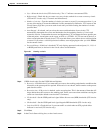
• Revertive—Check this box if you want traffic to revert to the working path when the conditions that
diverted it to the protect path are repaired. If Revertive is not chosen, traffic remains on the protect
path after the switch.
• Reversion time—If Revertive is checked, set the reversion time. This is the amount of time that will
elapse before the traffic reverts to the working path. Traffic can revert when conditions causing the
switch are cleared (the default reversion time is 5 minutes).
• SF threshold—Set the UPSR path-level signal failure bit error rate (BER) thresholds (STS circuits
only).
• SD threshold—Set the UPSR path-level signal degrade BER thresholds (STS circuits only).
• Switch on PDI-P—Check this box if you want traffic to switch when an STS payload defect
indicator is received (STS circuits only).
Step 5 Click Next.
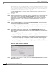
Step 6 In the Circuit Source dialog box, set the circuit source.
Options include node, slot, port, STS, and VT/DS-1. The options that display depend on the circuit type
and circuit properties you selected in Step 3 and the cards installed in the node. For example, if you are
creating a VT circuit or tunnel, only nodes with XCVT and XC10G cards are displayed. For Ethergroups,
see the “Ethernet Circuit Configurations” section on page 9-6.
Click Use Secondary Source if you need to create a UPSR bridge/selector circuit entry point in a
multivendor UPSR.
Step 7 Click Next.
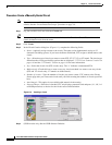
Step 8 In the Circuit Destination dialog box, enter the appropriate information for the circuit destination. If the
circuit is bidirectional, you can click Use Secondary Destination if you need to create a UPSR
bridge/selector circuit destination point in a multivendor UPSR. (To add secondary destinations to
unidirectional circuits, see “Create a Unidirectional Circuit with Multiple Drops” procedure on
page 6-8.)
Step 9 Click Next.
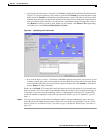
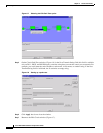
Step 10 Under Circuit Routing Preferences (Figure 6-2), de-select Route Automatically.
Step 11 If you want the circuit routed on a protected path, select Fully Protected Path. Otherwise, go to Step
12. CTC creates a primary and alternate circuit route (virtual UPSR) based on the nodal diversity option
you select:
• Nodal Diversity Required—Ensures that the primary and alternate paths within path-protected mesh
network (PPMN) portions of the complete circuit path are nodally diverse. (For information about
PPMN, see the “Path-Protected Mesh Networks” section on page 5-50.)
• Nodal Diversity Desired—Specifies that node diversity should be attempted, but if node diversity is
not possible, CTC creates link diverse paths for the PPMN portion of the complete circuit path.
• Link Diversity Only—Specifies that only link-diverse primary and alternate paths for PPMN
portions of the complete circuit path are needed. The paths may be node-diverse, but CTC does not
check for node diversity.
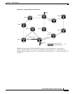
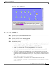
Step 12 Click Next. The Route Review and Edit panel is displayed for you to manually route the circuit. The
green arrows pointing from the source node to other network nodes indicate spans that are available for
routing the circuit.
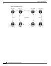
Step 13 Set the circuit route:
a. Click the arrowhead of the span you want the circuit to travel.
b. If you want to change the source STS or VT, change it in the Source STS or Source VT fields.