


5-36
Cisco ONS 15454 Installation and Operations Guide
78-13453-01
Chapter 5 SONET Topologies
Subtending Rings
d. Click Yes when prompted.
Step 4 From the node that will be deleted, remove the east and west span fibers. At this point, the node should
no longer be a part of the ring.
Step 5 Reconnect the span fibers of the nodes remaining in the ring.
Step 6 Open the Alarms tab of each newly-connected node and verify that the span cards are free of alarms.
Resolve any alarms before proceeding.
Step 7 One circuit at a time, delete and recreate each circuit that passed through the deleted node on different
STSs.
Note If the removed node was the BITS timing source, select a new node as the BITS source or
select another node as the master timing node.
Step 8 Use the “Switch UPSR Traffic” procedure on page 5-32 to clear the protection switch.
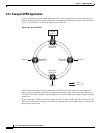
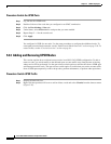
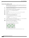
5.4 Subtending Rings
The ONS 15454 supports up to ten SONET DCCs. Therefore, one ONS 15454 node can terminate and
groom any one of the following ring combinations:
• 5 UPSRs, or
• 4 UPSRs and 1 BLSR, or
• 3 UPSRs and 2 BLSRs
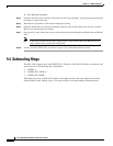
Subtending rings from an ONS 15454 reduces the number of nodes and cards required and reduces
external shelf-to-shelf cabling. Figure 5-28 shows an ONS 15454 with multiple subtending rings.