


6-17
Cisco ONS 15454 Installation and Operations Guide
November 2001
Chapter 6 Circuits and Tunnels
Cross-Connect Card Capacities
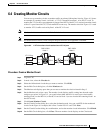
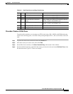
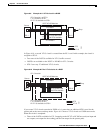
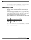
Figure 6-9 Example #1: A VT1.5 circuit in a BLSR
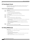
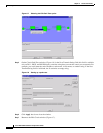
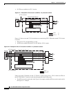
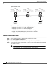
In Figure 6-10, a second VT1.5 circuit is created from the EC-1 card. In this example, the circuit is
assigned to STS-2:
• Two more of the 24 STSs available for VT1.5 traffic are used.
• 20 STSs are available on the XCVT or XC10G for VT1.5 circuits.
• STS-2 can carry 27 additional VT1.5 circuits.
Figure 6-10 Example #2: Two VT1.5 circuits in a BLSR
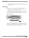
If you create VT1.5 circuits on nodes in UPSR or 1+1 protection, an additional STS is used for the
protect path at the source and drop nodes. Figure 6-11 shows a VT1.5 circuit at a UPSR source node.
When the circuit is completed:
• Three of the 24 STSs available for VT1.5 mapping on the XCVT or XC10G are used (one input and
two outputs, one output for the working path and one output for the protect path).
61846
STS Matrix
XCVT-XC10G Matrices
VT1.5 circuit #1 on STS-1
1 VT1.5 used on STS-1
27 VT1.5s available on STS-1
EC-1
Drop
2 STSs total used
22 STSs available
STS
VT1.5
VT1.5 Matrix
OC-12
Source
61847
STS Matrix
XCVT-XC10G Matrices
VT1.5 circuit #1
VT1.5 circuit #2 on STS-2
1 VT1.5 used on STS-2
27 VT1.5s available on STS-2
EC-1
4 STSs total used
20 STSs available
STS
VT1.5
OC-12
Drop
Source