


5-15
Cisco ONS 15454 Installation and Operations Guide
November 2001
Chapter 5 SONET Topologies
Bidirectional Line Switched Rings
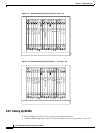
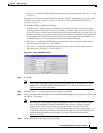
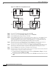
• East Port—Assign the east BLSR port for the node from the pull-down menu. (In Figure 5-11, this
is Slot 12.)
The east and west ports must match the fiber connections and DCC terminations set up in the “Install
the BLSR Trunk Cards” procedure on page 5-11 and the “Create the BLSR DCC Terminations”
procedure on page 5-13.
For four-fiber BLSRs, complete the following:
• Span Reversion—Set the amount of time that will pass before the traffic reverts to the original
working path following a span reversion. The default is 5 minutes. Span reversions can be set to
Never. If you set a reversion time, the times must be the same for both ends of the span. That is, if
Node A’s west fiber is connected to Node B’s east port, the Node A west span reversion time must
be the same as the Node B east span reversion time. To avoid reversion time mismatches, Cisco
recommends that you use the same span reversion time throughout the ring.
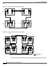
• West Protect—Assign the west BLSR port that will connect to the west protect fiber from the
pull-down menu. (In Figure 5-12, this is Slot 6.)
• East Protect—Assign the east BLSR port that will connect to the east protect fiber from the
pull-down menu. (In Figure 5-12, this is Slot 13.)
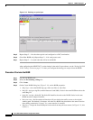
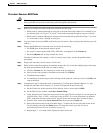
Figure 5-14 Setting BLSR properties
Step 5
Click OK.
Note Some or all of the following alarms display during BLSR setup: E-W MISMATCH, RING
MISMATCH, APSCIMP, APSDFLTK, BLSROSYNC. The alarms will clear after you
configure all the nodes in the BLSR.
Step 6 Complete Steps 2 – 5 at each node that you are adding to the BLSR.
Step 7 After you configure the last BLSR node, wait for the BLSR Ring Map Change dialog box to display (this
can take 10 – 30 seconds).
Note The dialog box will not display if SDCC Termination alarms (e.g., EOC) or BLSR alarms
(such as E-W MISMATCH and RING MISMATCH) are present. If an SDCC alarm is
present, review the DCC provisioning at each node; use the “Create the BLSR DCC
Terminations” procedure on page 5-13. If BLSR alarms have not cleared, repeat Steps 1 – 6
at each node, making sure each node is provisioned correctly. You can also following alarm
troubleshooting procedures provided in the Cisco ONS 15454 Troubleshooting and
Maintenance Guide.
Step 8 On the BLSR Ring Map Change dialog, click Yes.