


1-54
Cisco ONS 15454 Installation and Operations Guide
November 2001
Chapter 1 Hardware Installation
Cable Routing and Management
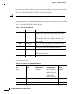
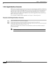
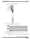
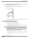
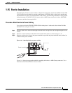
Step 1 Position the open slot of the fiber boot underneath the fiber cable.
Step 2 Push the fiber cable down into the fiber boot.
Step 3 Twist the fiber boot to lock the fiber cable into the tail end of the fiber boot.
Slide the fiber boot forward along the fiber cable until the fiber boot fits snugly onto the end of the SC
cable connector.
Figure 1-32 Attaching a fiber boot
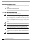
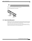
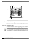
1.14 Cable Routing and Management
The ONS 15454 cable management facilities include the following:
• Cable management clips on optical card faceplates
• A cable-routing channel that runs the width of the shelf assembly
• Plastic horseshoe-shaped fiber guides at each side opening of the cable-routing channel that ensure
the proper bend radius is maintained in the fibers
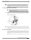
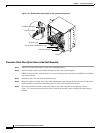
Note You can remove the fiber guide if necessary to create a larger opening (if you need to route Cat-5
Ethernet cables out the side, for example). To remove the fiber guide, take out the three screws that
anchor it to the side of the shelf assembly.
• A fold-down door that provides access to the cable-management tray
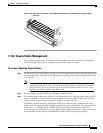
• Cable tie-wrap facilities on EIAs that secure cables to the cover panel
• Reversible jumper routing fins that enable you to route cables out either side by positioning the fins
as desired
• Jumper slack storage reels (2) on each side panel that reduce the amount of slack in cables that are
connected to other devices
Fiber boot
SC cable
connector
Fiber
optic
line
32092