


5-35
Cisco ONS 15454 Installation and Operations Guide
November 2001
Chapter 5 SONET Topologies
Unidirectional Path Switched Rings
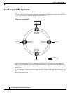
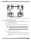
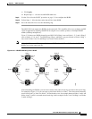
b. Remove the west fiber connection from the node that will connect to the east port of the new node.
Step 6 Replace the removed fiber connections with connections from the new node.
Note Perform this step on site at the new node.
Step 7 Log out of CTC and then log back in.
Step 8 Display the network view. The new node should appear in the network map. Wait for a few minutes to
allow all the nodes to appear.
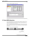
Step 9 Click the Circuits tab and wait for all the circuits to appear, including spans. The affected circuit will
display as “incomplete.”
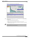
Step 10 In the network view, right-click the new node and select Update Circuits With New Node from the list
of options. Wait for the confirmation dialog box to appear. Verify that the number of updated circuits
displayed in the dialog box is correct.
Step 11 Select the Circuits tab and verify that no incomplete circuits are displayed. If incomplete circuits are
displayed, repeat Step 9.
Step 12 Use the “Switch UPSR Traffic” procedure on page 5-32 to clear the protection switch.
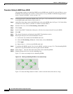
Procedure: Remove a UPSR Node
Caution The following procedure is designed to minimize traffic outages while nodes are removed, but traffic
will be lost when you delete and recreate circuits that passed through the removed node.
Step 1 Log into CTC and display the UPSR nodes in network view. Verify the following:
• All UPSR spans on the network map are green.
• No critical or major alarms (LOF, LOS, ASP, ASL) are displayed on the Alarms tab.
• On the Conditions tab, no UPSR switches are active.
• At each physical UPSR node, all fibers are securely connected to the appropriate ports.
If trouble is indicated, for example, a critical or major alarm exists, resolve the problem before
proceeding.
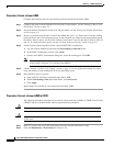
Step 2 Use the “Switch UPSR Traffic” procedure on page 5-32 to initiate a FORCE switch to switch traffic
away from the node you are removing. Initiate a FORCE switch on all spans connected to the node you
are removing.
Caution Traffic is not protected during a forced protection switch.
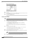
Step 3 In the node that will be removed, delete circuits that originate or terminate in that node. (If a circuit has
multiple drops, delete only the drops that terminate on the node you are deleting.)
a. Click the Circuits tab.
b. Select the circuit(s) to delete. To select multiple circuits, press the Shift or Ctrl key.
c. Click Delete.