


1-36
Cisco ONS 15454 Installation and Operations Guide
November 2001
Chapter 1 Hardware Installation
Coaxial Cable Installation
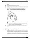
Procedure: Install Craft Interface Wires on the Backplane
Step 1 Use #22 or #24 AWG wire.
Step 2 Wrap the craft interface wires on the appropriate wire-wrap pins according to local site practice.
Note For information about attaching ferrites to wire-wrap pin fields, see the “Ferrite Installation”
section on page 1-61.
Step 3 Wrap the ground shield of the craft interface cable to the frame-ground pin.
Step 4 Wrap the ground wire of your computer cable to pin A3 on the craft pin field.
1.10 Coaxial Cable Installation
Caution Always use the supplied ESD wristband when working with a powered ONS 15454. Plug the
wristband cable into the ESD jack located on the lower-right outside edge of the shelf assembly.
When using ONS 15454 DS-3 electrical cables, the cables must terminate on an EIA installed on the
ONS 15454 backplane. EIAs are available with SMB and BNC connectors. All DS-3 cables connected
to the ONS 15454 DS-3 card must terminate with coaxial cables using the desired connector type to
connect to the specified EIA. For information about physically installing an EIA in the field, see the
“Install a BNC, High-Density BNC, or SMB EIA” procedure on page 1-22. For information about
coaxial cable management, see the “Coaxial Cable Management” section on page 1-57.
The electromagnetic compatibility (EMC) performance of the system depends on good-quality DS-3
coaxial cables, such as Shuner Type G 03233 D, or the equivalent.
1.10.1 BNC Connector Installation
For a description of BNC EIAs, see the “BNC EIA” section on page 1-17. The BNC connectors on the
EIA supports Trompeter UCBJ224 (75 Ohm) 4 leg connectors. Right-angle mating connectors for the
connecting cable are AMP 413588-2 (75 Ohm) connectors. If preferred, you can also use a straight
connector of the same type. Use RG-59/U cable to connect to the ONS 15454 BNC EIA. These cables
are recommended to connect to a patch panel and are designed for long runs of up to 450 feet.
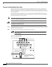
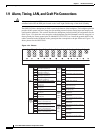
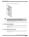
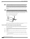
Procedure: Install Coaxial Cable With BNC Connectors
Step 1 Place the BNC cable connector over the desired connection point on the backplane.
Figure 1-25 shows how to connect a coaxial cable to the BNC EIA using a right-angle BNC cable
connector.
Step 2 Position the cable connector so that the slot in the connector is over the corresponding notch at the
backplane connection point.