


5-18
Cisco ONS 15454 Installation and Operations Guide
78-13453-01
Chapter 5 SONET Topologies
Bidirectional Line Switched Rings
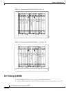
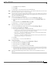
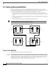
5.2.7 Adding and Removing BLSR Nodes
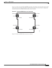
This section explains how to add and remove BLSR nodes. To add or remove a node, you force a
protection switch to route traffic away from the span where you will add or remove the node. Figure 5-15
shows a three-node BLSR before the new node is added. To add Node 3, you would:
• Force a protection switch on the Node 1 (Slot 5, West) and Node 4 (Slot 12, East) span. The
protection switch forces traffic away from the fibers that you will remove and reconnect to the added
node.
• Remove fibers from Node 1/Slot 5 and Node 4/Slot 12, then, using additional fibers, connect Node
1 and Node 4 to Node 3.
• Remove the protection switch to route traffic through the added node.
Note You can only add one node at a time to an ONS 15454 BLSR.
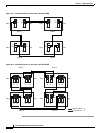
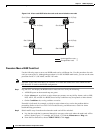
Figure 5-15 A three-node BLSR before adding a new node
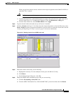
Procedure: Add a BLSR Node
Perform these steps on-site and not from a remote location.
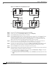
Step 1 Draw a diagram, similar to Figure 5-15, for the BLSR installation where you will add the node. In the
diagram, identify the nodes, cards (slots) and spans (east or west) that will connect to the new node. This
information is essential to complete this procedure without error. For example, in Figure 5-15, you
would circle Slot 5 (west) on Node 1, and Slot 12 (east) on Node 4.
68118
West East
West East
West East
West East
Slot 5
Tx
Rx
Slot 12
Tx
Rx
Node 3
Slot 5
Tx
Rx
Slot 12
Tx
Rx
Node 2Node 1
Slot 5
Tx
Rx
Slot 12
Tx
Rx
Node 4
Slot 5
Tx
Rx
Slot 12
Tx
Rx