


6-8
Cisco ONS 15454 Installation and Operations Guide
November 2001
Chapter 6 Circuits and Tunnels
Creating Multiple Drops for Unidirectional Circuits
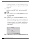
c. Click Add Span.
The span is added to the Included Spans list and the span arrow turns blue.
Step 14 Repeat Step 13 until the circuit is provisioned from the source to the destination node.
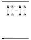
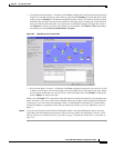
When provisioning a protected circuit, you only need to select one path of BLSR or 1+1 spans from the
source to the drop. If you select unprotected spans as part of the path, select two different paths for the
unprotected segment of the path.
Step 15 When the circuit is provisioned, click Finish.
If you entered more than 1 in Number of Circuits in the Circuit Attributes dialog box in Step 3, the
Circuit Source dialog box is displayed so you can create the remaining circuits.
Step 16 If you are provisioning circuits before installing the traffic cards and enabling their ports, you must
install the cards and enable the ports before circuits will carry traffic. For procedures, see the “Install
Optical, Electrical, and Ethernet Cards” procedure on page 1-48 and the “Enable Ports” procedure on
page 3-10.
6.3 Creating Multiple Drops for Unidirectional Circuits
Unidirectional circuits can have multiple drops for use in broadcast circuit schemes. In broadcast
scenarios, one source transmits traffic to multiple destinations, but traffic is not returned back to the
source.
When you create a unidirectional circuit, the card that does not have its backplane Rx input terminated
with a valid input signal generates a loss of service (LOS) alarm. To mask the alarm, create an alarm
profile suppressing the LOS alarm and apply it to the port that does not have its Rx input terminated.
See the “Creating and Modifying Alarm Profiles” section on page 10-9 for information.
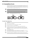
Procedure: Create a Unidirectional Circuit with Multiple Drops
Step 1 Use the “Create an Automatically Routed Circuit” procedure on page 6-2 to create a circuit. To make it
unidirectional, clear the Bidirectional check box on the Circuit Creation dialog box.
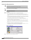
Step 2 After the unidirectional circuit is created, in node or network view select the Circuits tab.
Step 3 Select the unidirectional circuit and click Edit (or double-click the circuit).
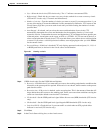
Step 4 On the Drops tab of the Edit Circuits dialog box, click Create or, if Show Detailed Map is selected,
right-click a node on the circuit map and select Add Drop.
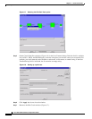
Step 5 On the Define New Drop dialog box, complete the appropriate fields to define the new circuit drop:
Node, Slot, Port, STS, VT (if applicable).
Step 6 Click OK.
Step 7 If you need to create additional drops, repeat Steps 4 – 6. If not, click Close.
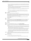
Step 8 Verify the new drops on the Edit Circuit map:
• If Show Detailed Map is selected: a “D” enclosed by circles appears on each side of the node
graphic.
• If Show Detailed Map is not selected: “Drop #1, Drop #2” appear under the node graphic.