


3-15
Cisco ONS 15454 Installation and Operations Guide
November 2001
Chapter 3 Node Setup
Setting Up ONS 15454 Timing
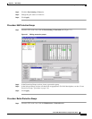
• Timing Mode—Set to External if the ONS 15454 derives its timing from a BITS source wired to the
backplane pins; set to Line if timing is derived from an OC-N card that is optically connected to the
timing node. A third option, Mixed, allows you to set external and line timing references. (Because
Mixed timing may cause timing loops, Cisco does not recommend its use. Use this mode with care.)
• SSM Message Set—Choose the message set level supported by your network. If a Generation 1 node
receives a Generation 2 message, the message will be mapped down to the next available Generation
1. For example, an ST3E message becomes an ST3.
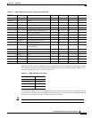
• Quality of RES—If your timing source supports the reserved S1 byte, you set the timing quality here.
(Most timing sources do not use RES.) Qualities are displayed in descending quality order as ranges.
For example, ST3<RES<ST2 means the timing reference is higher than a Stratum 3 and lower than
a Stratum 2. See Table 3-4 and Table 3-5 for more information.
• Revertive—If checked, the ONS 15454 reverts to a primary reference source after the conditions that
caused it to switch to a secondary timing reference are corrected.
• Revertive Time—If Revertive is checked, indicate the amount of time the ONS 15454 will wait
before reverting back to its primary timing source.
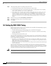
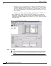
Step 3 In the BITS Facilities section, complete the following information:
Note The BITS Facilities section sets the parameters for your BITS1 and BITS2 timing references.
Many of these settings are determined by the timing source manufacturer. If equipment is
timed through BITS Out, you can set timing parameters to meet the requirements of the
equipment.
• State—Set the BITS reference to IS (In Service) or OOS (Out of Service). For nodes set to Line
timing with no equipment timed through BITS Out, set State to OOS. For nodes using External
timing or Line timing with equipment timed through BITS Out, set State to IS.
• Coding—Set to the coding used by your BITS reference, either B8ZS or AMI.
• Framing—Set to the framing used by your BITS reference, either ESF (Extended Super Frame, or
SF (D4) (Super Frame). SSM is not available with Super Frame.
• Sync Messaging—Check to enable SSM.
• AIS Threshold—Sets the quality level where a node sends an Alarm Indication Signal (AIS) from
the BITS 1 Out and BITS 2 Out backplane pins. When a node times at or below the AIS Threshold
quality, AIS is sent (used when SSM is disabled or frame is SF).
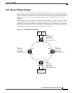
Step 4 Under Reference Lists, complete the following information:
Note Reference lists define up to three timing references for the node and up to six BITS Out
references. BITS Out references define the timing references used by equipment that can be
attached to the node’s BITS Out pins on the backplane. If you attach equipment to BITS Out
pins, you normally attach it to a node with Line mode because equipment near the External
timing reference can be directly wired to the reference.
• NE Reference—Allows you to define three timing references (Ref 1, Ref 2, Ref3). The node uses
Reference 1 unless a failure occurs to that reference, in which case, the node uses Reference 2. If
that fails, the node uses Reference 3, which is typically set to Internal Clock. This is the Stratum 3
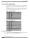
clock provided on the TCC+. The options displayed depend on the Timing Mode setting.
–
Timing Mode set to External—options are BITS1, BITS2, and Internal Clock.