


1-37
Cisco ONS 15454 Installation and Operations Guide
November 2001
Chapter 1 Hardware Installation
Coaxial Cable Installation
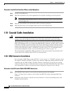
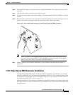
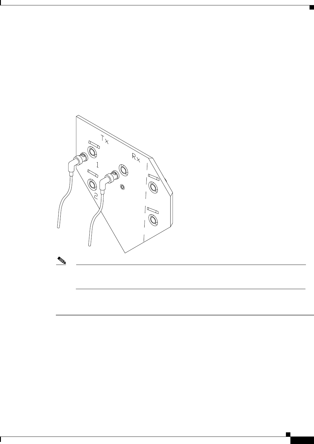
Step 3 Gently push the connector down until the notch backplane connector slides into the slot on the cable
connector.
Step 4 Turn the cable connector until the notch clicks into place.
Step 5 Tie wrap or lace the cables to the EIA according to Telcordia standards (GR-1275-CORE) or local site
practice.
Step 6 Route the cables to the nearest side of the shelf assembly through the side cutouts according to local site
practice. The rubber coated edges of the side cutouts prevent the cables from chafing.
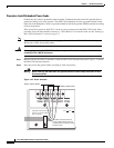
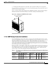
Figure 1-25 Using a right-angle connector to install coaxial cable with BNC connectors
Note Slots 1, 3, 15 and 17 are designated protection slots when BNC connectors are used. Slots 5,
6, 11, and 12 do not support DS3-12 cards when BNC connectors are used. A total of four
DS3-12 cards can be used to carry traffic with BNC connectors.
Step 7 Label all cables at each end of the connection to avoid confusion with cables that are similar in
appearance.
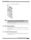
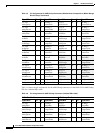
1.10.2 High-Density BNC Connector Installation
The High-Density BNC EIA supports Trompeter UCBJ224 (75 Ohm) 4 leg connectors. Use straight
connectors on RG-59/U cable to connect to the High-Density BNC EIA. Cisco recommends these cables
for connection to a patch panel; they are designed for long runs of up to 450 feet. For more detail, see
the “High-Density BNC EIA” section on page 1-18.
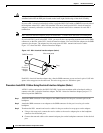
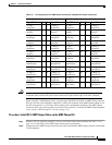
Although not required, Cisco strongly recommends using the BNC insertion tool to connect cables to the
EIA. Refer to the Cisco ONS 15454 Troubleshooting and Maintenance Guide for more information about
the insertion tool.
32075