


5-38
Cisco ONS 15454 Installation and Operations Guide
78-13453-01
Chapter 5 SONET Topologies
Subtending Rings
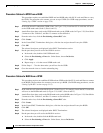
Procedure: Subtend a UPSR from a BLSR
This procedure requires an established BLSR and one BLSR node with OC-N cards and fibers to carry
the UPSR. The procedure also assumes you can set up a UPSR. (For UPSR setup procedures, see the
“Setting Up a UPSR” section on page 5-30.)
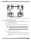
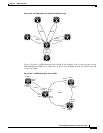
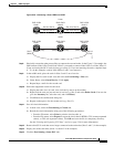
Step 1 In the node that will subtend the UPSR (Node 3 in Figure 5-29), install the OC-N cards that will serve
as the UPSR trunk cards (Node 3, Slots 6 and 13).
Step 2 Attach fibers from these cards to the UPSR trunk cards on the UPSR nodes. In Figure 5-29, Slot 6 Node
3 connects to Slot 13/Node 5, and Slot 13 connects to Slot 6/Node 6.
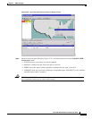
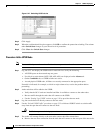
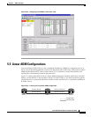
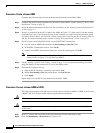
Step 3 From the node view, click the Provisioning > Sonet DCC tabs.
Step 4 Click Create.
Step 5 In the Create SDCC Terminations dialog box, click the slot and port that will carry the UPSR.
Step 6 Click OK.
The selected slots/ports are displayed in the SDCC Terminations section.
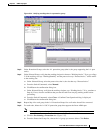
Step 7 Put the ports that you will use for the UPSR in service:
a. In the node view, double-click UPSR trunk card.
b. Select the Provisioning > Line tabs. Under Status, choose In Service.
c. Click Apply.
d. Repeat steps a - c for the second UPSR trunk card.
Step 8 Follow Steps 1 – 7 for the other nodes you will use for the UPSR.
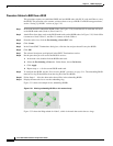
Step 9 Go to the network view to view the subtending ring.
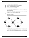
Procedure: Subtend a BLSR from a UPSR
This procedure requires an established UPSR and one UPSR node with OC-N cards and fibers to connect
to the BLSR. The procedure also assumes you can set up a BLSR. (For BLSR setup procedures, see the
“Setting Up BLSRs” section on page 5-10.)
Step 1 In the node that will subtend the BLSR (Node 3 in the Figure 5-29 example), install the OC-N cards that
will serve as the BLSR trunk cards (in Figure 5-29, Node 3, Slots 6 and 13).
Step 2 Attach fibers from these cards to the BLSR trunk cards on the BLSR nodes. In Figure 5-29, Slot 6/Node
3 connects to Slot 13/Node 5, and Slot 13 connects to Slot 6/Node 6.
Step 3 From the node view, click the Provisioning > Sonet DCC tabs.
Step 4 Click Create.
Step 5 In the Create SDCC Terminations dialog box, click the slot and port that will carry the BLSR.
Step 6 Click OK.
Step 7 The selected slots/ports are displayed under SDCC Terminations.
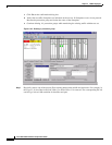
Step 8 Put the ports that you will use for the BLSR in service:
a. In the node view, double-click the BLSR trunk card.
b. Select the Provisioning > Line tabs. Under Status, choose In Service.