


5-16
Cisco ONS 15454 Installation and Operations Guide
78-13453-01
Chapter 5 SONET Topologies
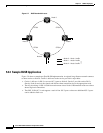
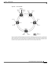
Bidirectional Line Switched Rings
Step 9 On the BLSR Ring Map dialog box, verify that the ring map contains all the nodes you provisioned in
the expected order. If so, click Accept. If the nodes do not appear, or are not in the expected order, repeat
Steps 1 – 8, making sure no errors are made.
Step 10 Switch to network view and verify the following:
• A green span line appears between all BLSR nodes
• All E-W MISMATCH, RING MISMATCH, APSCIMP, DFLTK, and BLSROSYNC alarms are
cleared.
Step 11 Test the BLSR using testing procedures normal for your site. Here are a few steps you can use:
a. Run test traffic through the ring.
b. Log into a node, click the Maintenance > Ring tabs, and choose MANUAL RING from the East
Switch list. Click Apply.
c. In network view, click the Conditions tab and click Retrieve. You should see a Ring Switch West
event, and the far-end node that responded to this request will report a Ring Switch East event.
d. Verify that traffic switches normally.
e. Choose Clear from the East Switch list and click Apply.
f. Repeat Steps a – d for the West Switch.
g. Disconnect the fibers at one node and verify that traffic switches normally.
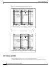
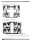
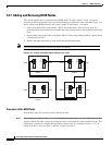
5.2.6 Upgrading From Two-Fiber to Four-Fiber BLSRs
Two-fiber OC-48 or OC-192 BLSRs can be upgraded to four-fiber BLSRs. To upgrade, you install two
OC-48 or OC-192 cards at each two-fiber BLSR node, then log into CTC and upgrade each node from
two-fiber to four-fiber. The fibers that were divided into working and protect bandwidths for the
two-fiber BLSR are now fully allocated for working BLSR traffic.
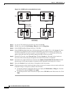
Procedure: Upgrade From a Two-Fiber to a Four-Fiber BLSR
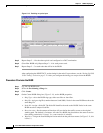
Step 1 Log into one of the two-fiber BLSR nodes. In network view:
a. Verify that all spans between BLSR nodes on the network map are green.
b. Click the Alarms tab. Verify that no critical or major alarms are present, nor any facility alarms,
such as LOS, LOF, AIS-L, SF, and SD. In a BLSR, these facility conditions may be reported as
minor alarms.
c. Click the Conditions tab, then click Retrieve Conditions. Verify that no ring switches are active.
If trouble is indicated, for example, a major alarm exists, resolve the problem before proceeding to
Step 2. See the Cisco ONS 15454 Troubleshooting and Maintenance Guide for additional information.
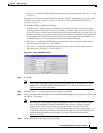
Step 2 Install two OC-48 or OC-192 cards at each BLSR node. You must install the same OC-N card rate as the
two fiber.
Step 3 Enable the ports for each new OC-N card:
a. Display the card in card view.
b. Click the Provisioning > Line tabs.