


2-18
Cisco ONS 15454 Installation and Operations Guide
November 2001
Chapter 2 Software Installation
Working with the CTC Window
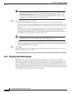
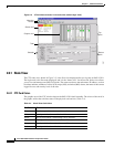
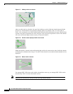
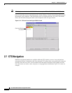
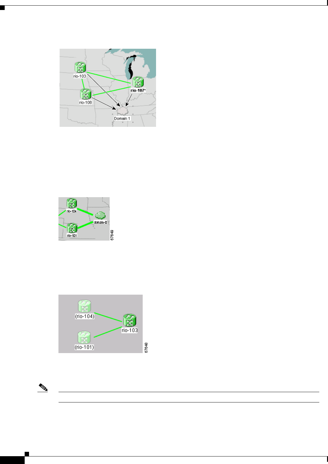
Figure 2-7 Adding nodes to a domain
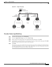
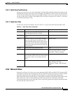
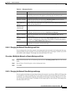
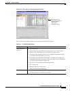
After you add a node to a domain, the span lines leading to nodes within the domain become thicker
(Figure 2-8). The thick lines may represent multiple spans. For example, if the “rio-104” node in
Figure 2-8 is connected to two nodes within domain-0, the thick line represents two spans. The thick line
is green if all spans it represents are active and grey if any one span it represents is down. The domain
icon color reflects the highest alarm severity of any node within it.
Figure 2-8 Outside nodes displayed within the domain
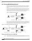
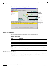
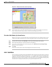
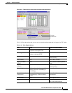
Within the domain, external nodes and domains that are directly connected to nodes inside the domain
are displayed in a dimmed color (Figure 2-9). DCC links with one or two ends inside the domain are also
displayed.
Figure 2-9 Nodes inside a domain
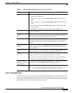
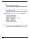
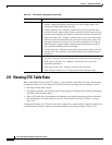
You manage ONS 15454s that reside within a domain the same way you manage ONS 15454s on the
network map. Table 2-8 shows the domain actions.
Note Domains you create will be seen by all users who log into the network.
55023