


5-30
Cisco ONS 15454 Installation and Operations Guide
78-13453-01
Chapter 5 SONET Topologies
Unidirectional Path Switched Rings
5.3.2 Setting Up a UPSR
To set up a UPSR, you perform four basic procedures:
• Install the UPSR trunk cards. Use the “Install the UPSR Trunk Cards” procedure on page 5-30
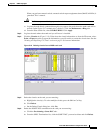
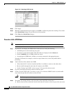
• Create the DCC terminations. Use the “Configure the UPSR DCC Terminations” procedure on
page 5-31.
• Configure the timing. Use the “Setting Up ONS 15454 Timing” section on page 3-12.
• Enable the ports. Use the “Enable the UPSR Ports” procedure on page 5-32.
After you enable the ports, you set up the UPSR circuits. UPSR signal thresholds—the levels that
determine when the UPSR path is switched—are set at the circuit level. To create UPSR circuits, see the
“Circuits Overview” section on page 6-1.
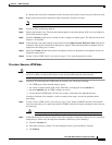
Procedure: Install the UPSR Trunk Cards
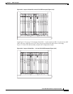
Step 1 Install the OC-N cards that will serve as the UPSR trunk cards. You can install the OC-3, OC-12, and
OC-48AS cards in any slot, but the OC-48 and OC-192 cards can only be installed in Slots 5, 6, 12, or 13.
Step 2 Allow the cards to boot.
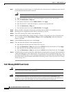
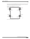
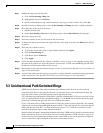
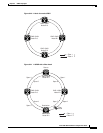
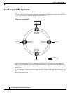
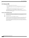
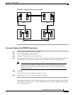
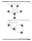
Step 3 Attach the fiber to the east and west UPSR ports at each node.
To avoid errors, make the east port the farthest slot to the right and the west port the farthest left. Fiber
connected to an east port at one node must plug into the west port on an adjacent node. Figure 5-25
shows fiber connections for a four-node UPSR with trunk cards in Slot 5 (west) and Slot 12 (east).
Always plug the fiber plugged into the transmit (Tx) connector of an OC-N card at one node into the
receive (Rx) connector of an OC-N card at the adjacent node. The card will display an SF LED if Tx and
Rx fibers are mismatched.