


5-17
Cisco ONS 15454 Installation and Operations Guide
November 2001
Chapter 5 SONET Topologies
Bidirectional Line Switched Rings
c. Click Status and choose In Service.
d. Click Apply.
e. Repeat Steps a – d for each new OC-N card at each BLSR node.
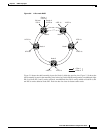
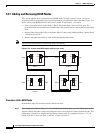
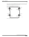
Step 4 Connect the fiber to the new cards. Use the same east – west connection scheme that was used to create
the two-fiber connections. Figure 5-12 shows an example.
Step 5 Test the new fiber connections using procedures standard for your site. For example, pull a Tx fiber for
a protect card and verify that an LOS alarm displays for the appropriate Rx card. Do this fiber test for
every span in the BLSR protect ring.
Step 6 Perform a span lockout at each BLSR node:
a. At one of the BLSR nodes, switch to node view. Click the Maintenance > Ring tabs.
b. Under West Switch for the two-fiber BLSR you will convert, select LOCKOUT SPAN. Click
Apply
c. Under East Switch, select LOCKOUT SPAN. Click Apply.
d. Repeat Steps a – c at each node in the two-fiber BLSR.
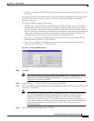
Step 7 Upgrade each node from two-fiber to four-fiber BLSR:
a. At one of the BLSR nodes, switch to node view. Click the Provisioning > Ring tabs.
b. Select the two-fiber BLSR. Click Upgrade.
c. On the Upgrade BLSR dialog box, complete the following:
–
Span Reversion—Set the amount of time that will pass before the traffic reverts to the original
working path following a span reversion. The default is 5 minutes.
–
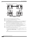
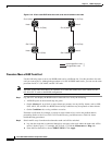
West Protect—Assign the east BLSR port that will connect to the east protect fiber from the
pull-down menu. (In Figure 5-12, this is Slot 6.)
–
East Protect—Assign the east BLSR port that will connect to the east protect fiber from the
pull-down menu. (In Figure 5-12, this is Slot 13.)
d. Click Ok.
e. Complete Steps a – d at each two-fiber BLSR node.
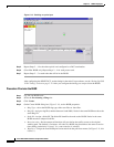
Step 8 Clear the span lockout:
a. Display a BLSR node in node view. Click the Maintenance > Ring tabs.
b. Under West Switch, select CLEAR. Click Apply
c. Under East Switch, select CLEAR. Click Apply.
d. Repeat Steps a – c at each node in the new four-fiber BLSR.
e. Switch to network view. Verify that no critical or major alarms are present, nor any facility alarms,
such as LOS, LOF, AIS-L, SF, and SD. If an alarm is present, resolve the problem using procedures
in the Cisco ONS 15454 Troubleshooting and Maintenance Guide.
Step 9 Test the four-fiber BLSR using procedures in Step 11 in the “Provision the BLSR” procedure on
page 5-14.