


5-46
Cisco ONS 15454 Installation and Operations Guide
78-13453-01
Chapter 5 SONET Topologies
Linear ADM Configurations
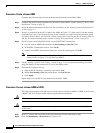
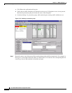
Step 15 In the SDCC Terminations section, click Create.
Step 16 In the Create SDCC Terminations dialog box, select the slot/port that had been the protect slot in the
linear ADM, for example, for Node 1, this would be Slot 5/Port 1 (OC-48).
Step 17 Click OK.
An EOC SDCC alarm will occur until an SDCC termination is created on the adjacent node.
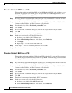
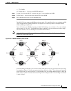
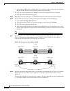
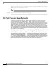
Step 18 Go to the node on the opposite end (Node 3 in the Figure 5-36 example) and repeat Steps 14 – 17.
Step 19 Delete and reenter the circuits one at a time. (See the “Creating Circuits and VT Tunnels” section on
page 6-2.)
Note Deleting circuits is traffic affecting.
You can create the circuits automatically or manually. However, circuits must be protected. When they
were built in the linear ADM, they were protected by the protect path on Node 1/Slot 5 to Node 2/Slot
5 to Node 3/Slot 13. With the new UPSR, circuits should also be created with protection.
Deleting the first circuit and recreating it to the same card/port should restore the circuit immediately.
Step 20 Monitor your SONET test set to verify that the circuit was deleted and restored.
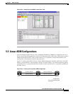
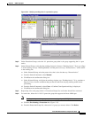
Step 21 You should also verify that the new circuit path for the clockwise (CW) fiber from Node 1 to Node 3 is
working. To do this, switch to network view and move your cursor to the green span between Node 1
and 3.
Although the cursor only shows the first circuit created, do not become alarmed that the other circuits
are not present. Verify with the SONET test set that the original circuits and the new circuits are
operational. The original circuits were created on the counter clockwise linear path.
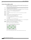
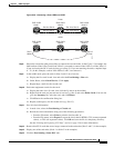
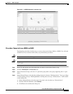
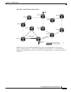
Step 22 Go to the network map to view the newly-created ring (Figure 5-37).