


1-49
Cisco ONS 15454 Installation and Operations Guide
November 2001
Chapter 1 Hardware Installation
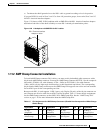
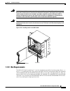
Card Installation
Step 2 Slide the card along the guide rails into the correct slot.
Step 3 Close the ejectors.
Step 4 Verify that power is applied to the shelf assembly.
Step 5 Verify the LED activity, as described in Table 1-10.
Step 6 Verify that the ACT or ACT/STBY LED is on. The signal fail (SF) LED can persist until all card ports
connect to their far end counterparts and a signal is present.
Step 7 When you have displayed CTC on your workstation, verify that the card appears in the correct slot on
the CTC node view. See Chapter 2, “Software Installation” for CTC information and setup instructions.
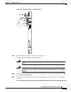
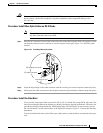
Procedure: Install the AIC Card
Step 1 Open the card ejectors.
Step 2 Slide the card along the guide rails into the correct slot.
Step 3 Close the ejectors.
Step 4 Verify that power is applied to the shelf assembly.
Step 5 Verify the that red FAIL LED remains lit for 1 second.
Step 6 Verify that the red FAIL LED blinks for 1 to 5 seconds.
Step 7 Verify that after 1 to 5 seconds, all LEDs blink once and turn off.
Step 8 Verify that the ACT LED is on.
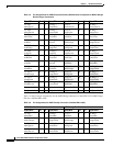
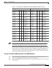
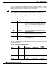
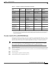
Table 1-10 LED Activity during Optical and Electrical Card Installation
Card Type LED Activity
OC-3, OC-12,
OC-48, OC-192
1. The red FAIL LED turns on and remains lit for 20 to 30 seconds.
2. The red FAIL LED blinks for 35 to 45 seconds.
3. All LEDs blink once and turn off for 5 to 10 seconds.
4. The ACT LED turns on.
DS-1, DS-3,
EC-1
1. The red FAIL LED turns on and remains lit for 10 to 15 seconds.
2. The red FAIL LED blinks for 30 to 40 seconds.
3. All LEDs blink once and turn off for 1 to 5 seconds.
4. The ACT/STBY LED turns on.
Ethernet
1. The red FAIL LED turns on and remains lit for 20 to 30 seconds.
2. The red FAIL LED blinks for 35 to 45 seconds.
3. All LEDs blink once and turn off for 1 to 5 seconds.
4. The ACT LED turns on.