


9-10
Cisco ONS 15454 Installation and Operations Guide
November 2001
Chapter 9 Ethernet Operation
Ethernet Circuit Configurations
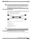
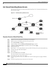
9.3.2 Shared Packet Ring Ethernet Circuits
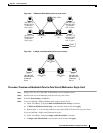
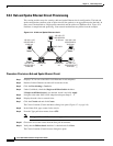
This section provides steps for creating a shared packet ring (Figure 9-9). Your network architecture may
differ from the example.
Figure 9-9 A shared packet ring Ethernet circuit
Procedure: Provision a Shared Packet Ring
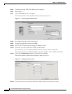
Step 1 Display CTC for one of the ONS 15454 Ethernet circuit endpoints.
Step 2 Double-click one of the Ethernet cards that will carry the circuit.
Step 3 Click the Provisioning > Card tabs.
Step 4 Under Card Mode, verify that Multi-card EtherSwitch Group is checked.
Step 5 If Multi-card EtherSwitch Group is not checked, check it and click Apply.
Step 6 Display the node view.
Step 7 Repeat Steps 2 – 6 for all other Ethernet cards in the ONS 15454 that will carry the shared packet ring.
Step 8 Navigate to the other ONS 15454 endpoint.
Step 9 Repeat Steps 2 – 7.
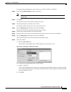
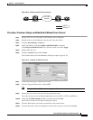
Step 10 Click the Circuits tab and click Create.
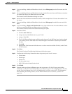
The Circuit Creation (Circuit Attributes) dialog box opens.
Step 11 In the Name field, type a name for the circuit.
Step 12 From the Type pull-down menu, choose STS. The VT and VT Tunnel types do not apply to Ethernet
circuits.
Step 13 From the Size pull-down menu, choose the size of the circuit.
ONS 15454ONS 15454
Access router
Backbone router
Access router
Access router
Access router
SONET Ring
Access router Access router
ONS 15454
32165
SONET
Ethernet