


1-2
Cisco ONS 15454 Installation and Operations Guide
November 2001
Chapter 1 Hardware Installation
Installation Overview
Warning
The ONS 15454 is intended for installation in restricted access areas. A restricted access area is
where access can only be gained by service personnel through the use of a special tool, lock, key,
or other means of security. A restricted access area is controlled by the authority responsible for
the location.
Warning
The ONS 15454 is suitable for mounting on concrete or other non-combustible surfaces only.
Caution Unused card slots should be filled with a blank faceplate (Cisco P/N 15454-BLANK). The blank
faceplate ensures proper airflow when operating the ONS 15454 without the front door attached,
although Cisco recommends that the front door remain attached.
Note The ONS 15454 is designed to comply with GR-1089-CORE Type 2 and Type 4. Install and operate
the ONS 15454 only in environments that do not expose wiring or cabling to the outside plant.
Acceptable applications include Central Office Environments (COEs), Electronic Equipment
Enclosures (EEEs), Controlled Environment Vaults (CEVs), huts, and Customer Premise
Environments (CPEs).
1.1 Installation Overview
When installed in an equipment rack, the ONS 15454 assembly is typically connected to a fuse and alarm
panel to provide centralized alarm connection points and distributed power for the ONS 15454. Fuse and
alarm panels are third-party equipment and are not described in this documentation. If you are unsure
about the requirements or specifications for a fuse and alarm panel, consult the documentation for the
related equipment. The front door of the ONS 15454 allows access to the shelf assembly, fan-tray
assembly, and cable-management area. The backplanes provide access to alarm contacts, external
interface contacts, power terminals, and BNC/SMB connectors.
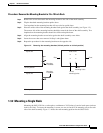
Warning
The ONS 15454 relies on the protective devices in the building installation to protect against short
circuit, overcurrent, and grounding faults. Ensure that the protective devices are properly rated to
protect the system, and that they comply with national and local codes.
Warning
Incorporate a readily-accessible, two-poled disconnect device in the fixed wiring.
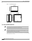
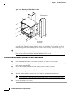
You can mount the ONS 15454 in a 19- or 23-inch rack. The shelf assembly weighs approximately 55
pounds with no cards installed and features a front door for added security, a fan tray module for cooling,
and extensive cable-management space.
ONS 15454 optical cards have SC connectors on the card faceplate. Fiber optic cables are routed into
the front of the destination cards. Electrical cards (DS-1, DS-3, DS3XM-6, and EC-1) require electrical
interface assemblies (EIAs) to provide the cable connection points for the shelf assembly. In most cases,
EIAs are ordered with the ONS 15454 and come pre-installed on the backplane. See the “Backplane
Access” section on page 1-14 for more information about the EIAs.