


5-3
Cisco ONS 15454 Installation and Operations Guide
November 2001
Chapter 5 SONET Topologies
Bidirectional Line Switched Rings
The SONET K1 and K2 bytes carry the information that governs BLSR protection switches. Each BLSR
node monitors the K bytes to determine when to switch the SONET signal to an alternate physical path.
The K bytes communicate failure conditions and actions taken between nodes in the ring.
If a break occurs on one fiber, working traffic targeted for a node beyond the break switches to the
protect bandwidth on the second fiber. The traffic travels in reverse direction on the protect bandwidth
until it reaches its destination node. At that point, traffic is switched back to the working bandwidth.
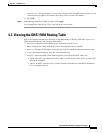
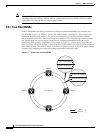
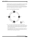
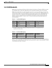
Figure 5-2 shows a sample traffic pattern on a four-node, two-fiber BLSR.
Figure 5-2 Four-node, two-fiber BLSR sample traffic pattern
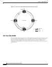
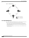
Figure 5-3 shows how traffic is rerouted following a line break between Node 0 and Node 3.
• All circuits originating on Node 0 carried to Node 2 on Fiber 2 are switched to the protect bandwidth
of Fiber 1. For example, a circuit carried on STS-1 on Fiber 2 is switched to STS-25 on Fiber 1. A
circuit carried on STS-2 on Fiber 2 is switched to STS-26 on Fiber 1. Fiber 1 carries the circuit to
Node 3 (the original routing destination). Node 3 switches the circuit back to STS-1 on Fiber 2
where it is routed to Node 2 on STS-1.
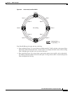
• Circuits originating on Node 2 that were normally carried to Node 0 on Fiber 1 are switched to the
protect bandwidth of Fiber 2 at Node 3. For example, a circuit carried on STS-2 on Fiber 1 is
switched to STS-26 on Fiber 2. Fiber 2 carries the circuit to Node 0 where the circuit is switched
back to STS-2 on Fiber 1 and then dropped to its destination.
Node 0
Node 1
Traffic flow
Node 2
Node 3 OC-48 Ring
Fiber 1
Fiber 2
61956