


1-41
Cisco ONS 15454 Installation and Operations Guide
November 2001
Chapter 1 Hardware Installation
DS-1 Cable Installation
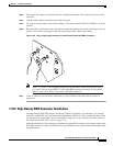
c. Terminate the shield ground wire on the DS-1 cable to ground according to local site practice.
If you put DS1N-14 cards in Slots 3 and 15 to form 1:N protection groups, do not wire Slots 3 and 15
for DS-1 electrical interface adapters.
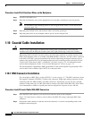
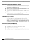
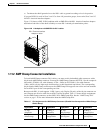
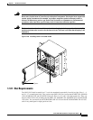
Figure 1-28 shows a ONS 15454 backplane with an SMB EIA with DS-1 electrical interface adapters
attached on both sides of the shelf assembly to create DS-1 twisted-pair termination points.
Figure 1-28 A backplane with SMB EIA for DS-1 cables
1.11.2 AMP Champ Connector Installation
To install AMP Champ connector DS-1 cables, you must use 64-pin bundled cable connectors with a
64-pin male AMP Champ connector. You need an AMP Champ connector #552276-1 for the receptacle
side and #1-552496-1 (for cable diameter .475in.–.540in) or #2-552496-1 (for cable diameter
.540in.–.605in.) for the right-angle shell housing (or their functional equivalent). The corresponding
64-pin female AMP Champ connector on the AMP Champ EIA supports one receive and one transmit
for each DS-1 port for the corresponding card slot.
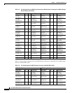
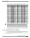
Because each DS1-14 card supports 14 DS-1 ports, only 56 pins (28 pairs) of the 64-pin connector are
used. Prepare one 56-wire cable for each DS-1 facility installed. Table 1-5 shows the pin assignments
for the AMP Champ connectors on the ONS 15454 AMP Champ EIA. See the “AMP Champ EIA”
section on page 1-20 for more information about the AMP Champ EIA.
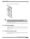
32085
DS-1 Electrical Interface
Adapter or balun
Table 1-5 Pin Assignments for AMP Champ Connectors (Shaded Area Corresponds to White/Orange
Binder Group)
Signal/Wire Pin Pin Signal/Wire Signal/Wire Pin Pin Signal/Wire
Tx Tip 1
white/blue
1 33 Tx Ring 1
blue/white
Rx Tip 1
yellow/orange
17 49 Rx Ring 1
orange/yellow
Tx Tip 2
white/orange
2 34 Tx Ring 2
orange/white
Rx Tip 2
yellow/green
18 50 Rx Ring 2
green/yellow