


1-15
Cisco ONS 15454 Installation and Operations Guide
November 2001
Chapter 1 Hardware Installation
Backplane Access
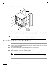
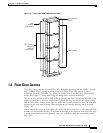
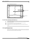
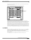
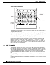
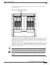
Figure 1-10 Backplane sheet metal covers
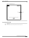
Procedure: Remove the Backplane Sheet Metal Covers
Step 1 To remove the lower backplane cover, loosen the five screws that secure it to the ONS 15454 and pull it
away from the shelf assembly.
Step 2 Loosen the nine perimeter screws that hold the backplane sheet metal cover(s) in place.
Step 3 Lift the panel by the bottom to remove it from the shelf assembly.
Step 4 Store the panel for later use. Attach the backplane sheet metal cover(s) whenever EIA(s) are not
installed.
1.5.1 Lower Backplane Cover
The lower section of the ONS 15454 backplane is covered by a clear plastic protector, which is held in
place by five 6-32 x 1/2 inch screws. Remove the lower backplane cover to access the alarm interface
panel (AIP), alarm pin field, frame ground, and power terminals.
BA
32074
Lower Backplane
Cover
Backplane Sheet Metal
Covers