


5-24
Cisco ONS 15454 Installation and Operations Guide
78-13453-01
Chapter 5 SONET Topologies
Bidirectional Line Switched Rings
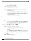
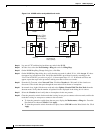
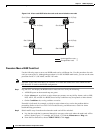
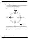
Figure 5-18 A four-node BLSR after the trunk cards are switched at one node
Procedure: Move a BLSR Trunk Card
Use the following steps to move one BLSR trunk card to a different slot. Use this procedure for each
card you want to move. Although the procedure is for OC-48 BLSR trunk cards, you can use the same
procedure for OC-12, OC-48AS, and OC-192 cards.
Note The ONS 15454 nodes must have CTC Release 2.0 or later and cannot have active alarms for the
OC-48 or OC-12 cards or the BLSR configuration.
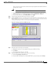
Step 1 Log into CTC and display the BLSR nodes in network view. Verify the following:
• All BLSR spans on the network map are green.
• On the Alarms tab, no critical or major alarms are present, nor any facility alarms, such as LOS,
LOF, AIS-L, SF, and SD. In a BLSR, these facility conditions may be reported as minor alarms.
• On the Conditions tab, no ring switches are active.
If trouble is indicated, for example, a critical or major alarm exists, resolve the problem before
proceeding. Refer to the Cisco ONS 15454 Troubleshooting and Maintenance Guide for alarm
troubleshooting procedures.
Step 2 Switch traffic away from the node where the trunk card will be switched:
a. Log into the node that is connected through its east port to the node where the trunk card will be
moved. (In the Figure 5-17 example, this is Node 1.) Click the Maintenance > Ring tabs.
b. From the East Switch list, choose FORCE RING. Click Apply.
67551
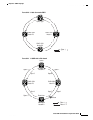
Node 1
Node 4
Node 3
Node 2
Slot 12 (East)
Slot 6 (West)
Slot 6 (East)
Slot 5 (West)
Slot 12 (East)
Slot 6 (West)
Slot 12 (East)
Slot 6 (West)
Unchanged fiber route
Changed fiber route