


9-9
Cisco ONS 15454 Installation and Operations Guide
November 2001
Chapter 9 Ethernet Operation
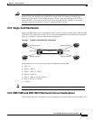
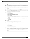
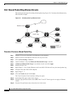
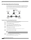
Ethernet Circuit Configurations
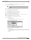
Step 14 If you are building a Multicard EtherSwitch circuit, choose Ethergroup from the Slot menu and click
Next.
Step 15 If you are building a Single-card EtherSwitch circuit, from the Slot menu choose the Ethernet card where
you enabled the single-card Etherswitch and click Next.
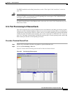
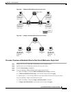
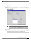
The Circuit Creation (Destination) dialog box opens.
Step 16 Choose the circuit destination from the Node menu, in this example Node 2. Choose the node that is not
the source.
Step 17 If you are building a Multicard EtherSwitch circuit choose Ethergroup from the Slot menu and click
Next.
Step 18 If you are building a Single-card EtherSwitch circuit, from the Slot menu choose the Ethernet card for
which you enabled the Single-card Etherswitch and click Next.
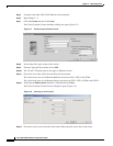
The Circuit Creation (Circuit VLAN Selection) dialog box opens.
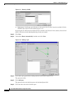
Step 19 Create the VLAN:
a. Click the New VLAN tab.
b. Assign an easily-identifiable name to your VLAN.
c. Assign a VLAN ID.
d. The VLAN ID should be the next available number between 2 and 4093 that is not already assigned
to an existing VLAN. Each ONS 15454 network supports a maximum of 509 user-provisionable
VLANs.
e. Click OK.
f. Highlight the VLAN name and click the arrow >> tab to move the available VLAN(s) to the Circuit
VLANs column.
Step 20 Click Next.
The Circuit Creation (Circuit Routing Preferences) dialog box opens.
Step 21 Confirm that the following information about the point-to-point circuit is correct:
• Circuit name
• Circuit type
• Circuit size
• VLANs on the circuit
• ONS 15454 nodes included in the circuit
Step 22 Click Finish.
Step 23 You now need to provision the Ethernet ports and assign ports to VLANs. For port provisioning
instructions, see the “Provision Ethernet Ports” procedure on page 9-3. For assigning ports to VLANs,
see the “Provision Ethernet Ports for VLAN Membership” procedure on page 9-24. For information
about manually provisioning circuits, see the “Ethernet Manual Cross-Connects” procedure on
page 9-16.