


1-44
Cisco MGX 8800/8900 Series Hardware Installation Guide
Releases 2 - 5.2, Part Number OL-4545-01, Rev. H0, May 2006
Chapter 1 Product Overviews
Cisco MGX 8950 Switch
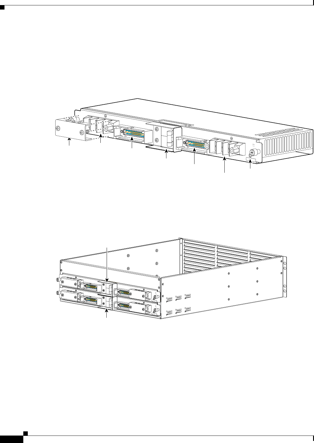
DC Power Entry Module
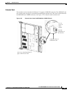
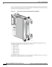
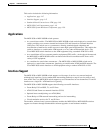
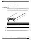
The MGX 8950 can accept power from a –48 VDC (–42 + –56 VDC) DC source that connects to one
(primary) or two (secondary/redundant) –48 VDC PEMs. Each primary or redundant DC source
connects to one DC PEM in the system. Each DC PEM accepts two 100 A service feeds from the same
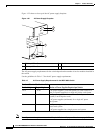
DC source. Figure 1-28 shows a close-up of the DC PEM.
Figure 1-28 MGX 8950 DC PEM
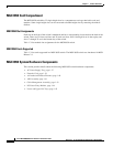
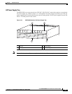
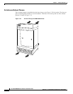
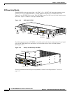
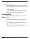
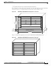
For a DC-powered system, the DC PEMs are installed at the back of the air intake plenum. If you install
only one DC PEM, install it on the bottom, as viewed from the rear of the air intake plenum.
(See Figure 1-29.)
Figure 1-29 Primary and Secondary DC PEMs
For more information about DC power requirements, see the “Power Requirements” section on
page 3-17.
DC
J2 output
connector
-48V DC
-48V DC 50A
-48V
RTN
J2
J1
-48V DC 50A
-48V
RTN
43978
Circuit breaker
J1 output
connector
DC OK
LED
Plastic
cover
Terminal
block 2
Terminal
block 1
-4
8
V
D
C
5
0
A
D
C
D
C
-4
8
V
D
C
5
0
A
-4
8
V
R
T
N
J2
J
1
-4
8
V
D
C
5
0
A
-4
8
V
R
T
N
-4
8
V
D
C
5
0
A
-4
8
V
D
C
5
0
A
-4
8
V
R
T
N
J
2
J
1
-4
8
V
D
C
5
0
A
-4
8
V
R
T
N
43975
Secondary PEM
Primary PEM