


3-49
Cisco MGX 8800/8900 Series Hardware Installation Guide
Releases 2 - 5.2, Part Number OL-4545-01, Rev. H0, May 2006
Chapter 3 Preparing for Installation
Site Requirements for a MGX 8830 or MGX 8830/B Switch
DC power sources must be dedicated DC branch circuits. Each branch circuit must be protected by a
dedicated circuit breaker. The circuit breaker must have a rated trip delay time greater than that of the
MGX 8830 or MGX 8830/B switch circuit breaker.
The MGX 8830 or MGX 8830/B switch uses a 30-A, 1-pole circuit breaker with a short trip delay on
each –48 V input. It is recommended that the site have a dedicated 30-A, 1-pole circuit breaker with a
medium trip delay at each branch circuit.
Connect the safety grounding wire to a solid earth ground. It is recommended that you use a ring terminal
lug to terminate the ground conductor at the ground stud. For details, see the “Bonding and Grounding
the Cisco MGX System” section on page C-8.
Caution The –48 VDC return, logical grounds, and safety grounds are connected to the equipment chassis;
therefore, you must use a low-impedance connector to connect the chassis ground to the earthing ground.
Note Connect the MGX 8830 or MGX 8830/B switch only to a –48 VDC source that complies with the SELV
requirements in UL 1950, IEC 950, EN 60950, and CSA C22.2 No. 950-95.
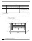
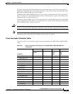
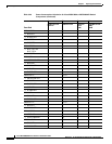
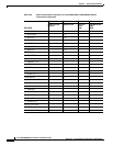
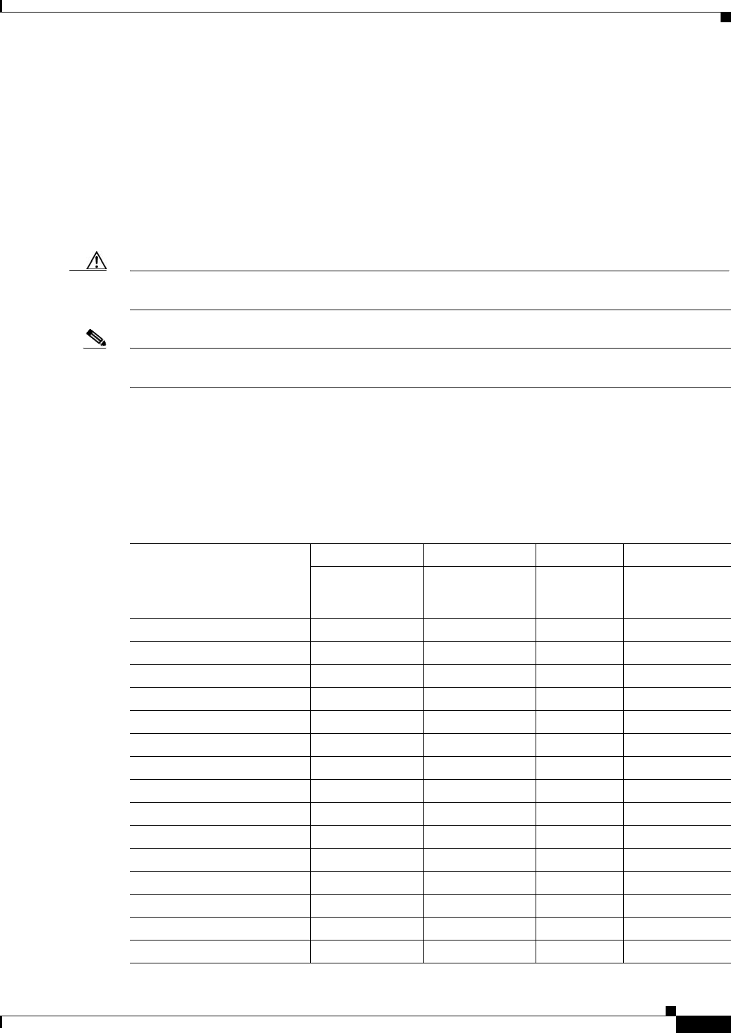
Power Consumption Calculation Tables
You can use Table 3-20 to calculate the typical power requirement for a MGX 8830 or MGX 8830/B
switch.
Table 3-20 Power Consumption Calculation for Cisco MGX 8830 or MGX 8830/B Switch
Components
Front Card
ABCD
Number of Cards
Installed
Watts Per Card Total Card
Power
(AxB)
Total 48V Current
(ADC)
(C/48)
AUSM-8E1/B 28.22
• MGX-RJ48-8E1 3
• RJ48-8E1 3
• R-RJ48-8E1 3
• SMB-8E1 5
• R-SMB-8E1 5
AUSM-8T1/B 28.22
• RJ48-8T1 3
• R-RJ48-8T1 3
CESM-8E1 29.1
• MGX-RJ48-8E1 3
• RJ48-8E1 3
• R-RJ48-8E1 3
• SMB-8E1 5
• R-SMB-8E1 5