


1-32
Cisco MGX 8800/8900 Series Hardware Installation Guide
Releases 2 - 5.2, Part Number OL-4545-01, Rev. H0, May 2006
Chapter 1 Product Overviews
Cisco MGX 8850 and MGX 8850/B Switches
Exhaust Plenum
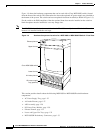
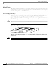
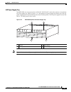
The exhaust plenum is installed above the upper fan tray (see Figure 1-9 for location). The fan trays pull
air from the air intake plenum up through the modules to cool the modules. Then the air is forced up and
out of the exhaust plenum, as shown in Figure 1-12.
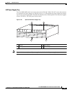
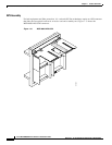
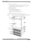
Lower and Upper Fan Trays
Each fan tray houses nine fans that provide system cooling. The MGX 8850 or MGX 8850/B switch
requires that two fan trays (upper and lower) be installed when the system is in operation.
Figure 1-9 shows the location of the lower and upper fan trays in a system. Figure 1-17 shows the rear
view of the fan tray.
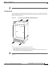
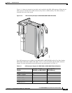
Caution When a fan tray is installed, the arrow on the air flow direction label on the back of the fan tray should
point up.
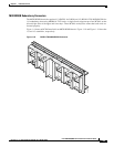
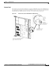
Figure 1-17 Fan Tray—Rear View
When the switch is shipped pre-installed in a Cisco-supplied cabinet, the fan trays are installed in the
cabinet as well.
Caution If a fan tray fails, replace it immediately.
66951
UP
AIR FLOW
DIRECTION