


5-101
Cisco MGX 8800/8900 Series Hardware Installation Guide
Releases 2 - 5.2, Part Number OL-4545-01, Rev. H0, May 2006
Chapter 5 Installing the Cisco MGX Switch or Gateway
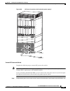
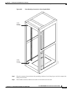
Installing the MGX 8830 or MGX 8830/B Switch
Installation Procedures
Caution The switch should not receive power while you install the components.
The following sections detail the installation procedures for a MGX 8830 system:
• “Install Stability Plate for Seismic Anchoring” section on page 5-101
• “Ground the Frame Bonding Ground Connection for a Cisco-Supplied Rack” section on page 5-104
• “Measure Rack Space” section on page 5-106
• “Prepare for Rack Installation” section on page 5-107
• “Install the AC Power Supply Tray” section on page 5-108
• “Install the MGX 8830 Switch without a Mechanical Lift” section on page 5-109
• “Install the MGX 8830 Switch with a Mechanical Lift” section on page 5-118
• “Install the Cable Management Assembly” section on page 5-122
• “Connect the AC Power Supply Tray to the MGX 8830 Switch” section on page 5-122
• “Connect the Back Cards” section on page 5-124
• “Connect the Console Port” section on page 5-124
• “Connect Power to the MGX 8830 Switch” section on page 5-126
• “Connect the External Clock” section on page 5-130
• “Connect the Alarms” section on page 5-130
• “Connect the MP Connection” section on page 5-131
• “Connect the LAN1/2 Ports” section on page 5-132
• “Verify EMI Compliance” section on page 5-132
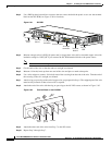
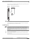
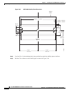
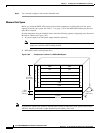
Install Stability Plate for Seismic Anchoring
You can anchor your Cisco-supplied rack or cabinet to the floor with an optional stability plate designed
for seismic anchoring.
Note These instructions are specific to a Cisco-supplied cabinet, but can be used for anchoring a
Cisco-supplied rack. If you are not installing your system in a Cisco-supplied rack or cabinet, anchor
your third-party rack or vendor cabinet according to guidelines in the third-party vendor documentation.
The slots in the stability plate use up to 5/8-inch anchor bolts.
Caution When moving a Cisco-supplied cabinet, do not push the cabinet at its sides. Instead, grip the front or
back edges of the cabinet.
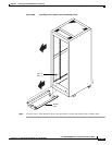
Complete the following steps to anchor your Cisco cabinet to a stability plate:
Step 1 Drill holes into the floor to install the stability plate. See Figure 5-65 for the dimensions.