


2-68
Cisco MGX 8800/8900 Series Hardware Installation Guide
Releases 2 - 5.2, Part Number OL-4545-01, Rev. H0, May 2006
Chapter 2 Illustrated Card List for MGX Switches and the MGX 8880 Media Gateway
Front Cards
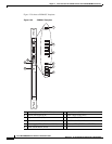
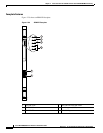
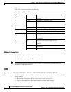
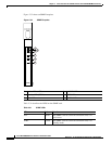
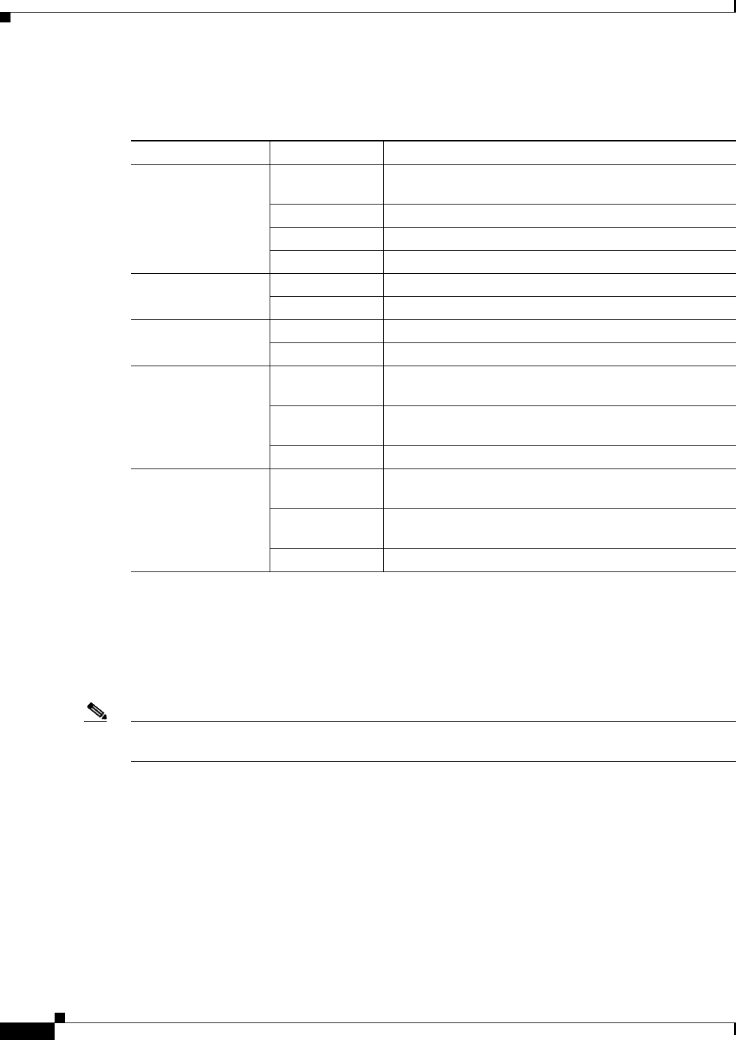
Table 2-28 describes the LEDs on the RPM-XF.
Module Configurations
The RPM-XF supports the following module configurations:
• Standalone.
• 1:N card set redundancy—No SRM is required.
Note For module configuration information, refer to Chapter 4, “Planning for Card Redundancy, Line
Redundancy, and Bulk Distribution”.
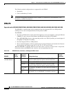
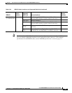
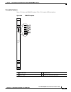
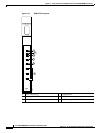
SRM
Supported models: MGX 8850 (PXM1E/PXM45), MGX 8850/B (PXM1E/PXM45), MGX 8830, MGX 8830/B, MGX 8880
The Service Resource Module (SRM) is a single-height card that provides three main functions for the
service modules:
• Bit Error Rate Testing. See “Bit Error Rate Testing” section on page 2-75
• 1:N Card Set Redundancy—MGX 8850 (PXM45) and MGX 8850 (PXM1E)
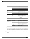
Table 2-28 RPM-XF LEDs
LED Status Description
CPU OK Green The RPM-XF card set (front card and back cards) is in the
active state.
Yellow The RPM-XF is in Standby mode.
Red The RPM-XF has failed.
Off The CPU is not operational.
CB TX Green Cells are being transmitted to the cell bus.
Off Cells are not being transmitted to the cell bus.
CB RX Green Cells are being received from the cell bus.
Off Cells are not being received from the cell bus.
LM1 OK Green There is a back card in the upper rear bay and the cable is
connected.
Red There is a back card in the upper rear bay but the cable is
not connected.
Off There is no back card in the upper rear bay.
LM2 OK Green There is a back card in the lower rear bay and the cable is
connected.
Red There is a back card in the lower rear bay but the cable is
not connected.
Off There is no back card in the lower rear bay.