


5-44
Cisco MGX 8800/8900 Series Hardware Installation Guide
Releases 2 - 5.2, Part Number OL-4545-01, Rev. H0, May 2006
Chapter 5 Installing the Cisco MGX Switch or Gateway
Installing the MGX 8850 (PXM1E/PXM45) Switch, MGX 8850/B or MGX 8880 Media Gateway
Warning
Do not touch the power supply when the power cord is connected. For systems with a power switch,
line voltages are present within the power supply even when the power switch is off and if the power
cord is connected. For systems without a power switch, line voltages are present within the power
supply when the power cord is connected.
Statement 4
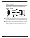
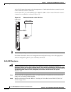
Connect AC Power to the Switch
Complete the following steps to connect AC power to the switch.
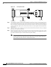
Note The AC power receptacle on the AC power supply tray is an IEC-type with a clamp. The AC voltage
range is 180 to 254 VAC. See Table 3-7 for information about the types of AC power cords.
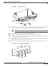
Step 1 Loosen the cable clamp around the AC receptacle on the AC power supply tray to allow clearance for
the cable connector.
Step 2 Firmly seat the cable plug in the AC receptacle on the back of the AC power supply tray.
Step 3 Tighten the clamp.
Caution Verify that the branch circuit power is off before you insert the power cable into the wall outlet.
Step 4 Plug the other end of the AC power cord into the wall outlet.
Step 5 Turn on the power source and turn the power switch on.
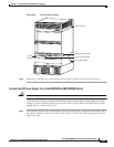
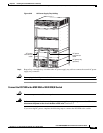
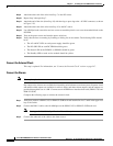
Step 6 Verify that the fans are running by listening or feeling for air movement. The following LEDs should
be lit:
• The AC and DC LEDs on each power supply should be green.
• The Status LED on the PXM1Es or PXM45s should be green.
• The Standby LED on each service module should be yellow.
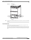
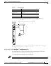
Connect DC Power to the Switch
Complete the following steps to connect DC power to the switch.
Note Connect the MGX 8850 or MGX 8850/B switch only to a –48-VDC source that complies with the Safety
Extra Low Voltage (SELV) requirements in UL 1950, IEC 950, EN 60950, and CSA C22.2 No. 950-95.
If you are installing redundant DC PEMs, you can connect to the same power source if you do not require
the additional fault tolerance offered when separate power sources are used.
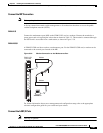
Step 1 Verify that the power source to the switch is turned off and that the circuit breaker on the DC PEM is off.
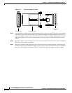
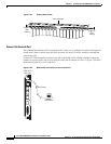
Step 2 Use a Phillips-head screwdriver to remove the two screws that hold the plastic cover over the terminal
block on the DC PEM (see Figure 5-28 for location).