


3-18
Cisco MGX 8800/8900 Series Hardware Installation Guide
Releases 2 - 5.2, Part Number OL-4545-01, Rev. H0, May 2006
Chapter 3 Preparing for Installation
Site Requirements for the MGX 8850 or MGX 8850/B Switch
The following sections provide additional information about power:
• AC Power, page 3-18
• DC Power, page 3-19
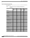
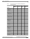
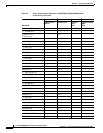
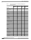
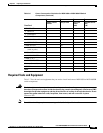
• Power Consumption Calculation Tables, page 3-20
AC Power
AC power is supplied to the MGX 8850 or MGX 8850/B switch through the AC power supply tray. AC
power sources must be dedicated AC branch circuits.
Each branch circuit must be protected by a dedicated two-pole circuit breaker. The circuit breakers at the
source must have a rated trip delay time greater than those of the MGX 8850 switch circuit breaker with
a medium trip delay.
The MGX 8850 or MGX 8850/B switch uses a 20-A, 2-pole circuit breaker for each AC input. It is
recommended that the site have a 20-A, 2-pole AC circuit breaker with a long trip delay at each branch
circuit.
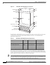
Note For more information about the AC power supply tray, see the “AC Power Supply Tray” section on
page 1-25.
Tip Check the power at your site to ensure that you are receiving “clean” power (free of spikes and noise).
Install a power conditioner if necessary.
Caution Consult Cisco Customer Service if the plans for the system’s AC power include an uninterruptible power
source (UPS). It is recommended that you use a UPS with a low output impedance and the capacity to
provide the necessary fault current to trip the protection devices. If the UPS cannot provide the fault
current, the UPS must be equipped with a fault bypass switch that can trip the protection devices through
the utility power. Do not use a UPS or any power source with a Ferro-Resonant transformer.
Caution For mission-critical applications, it is recommended that you use the dual AC power input tray with dual
AC power cords, so that there can be no single or primary power failure.
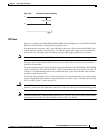
The power receptacles to which the switch connects must be of the grounding type. The grounding
conductors that connect to the receptacles should connect to protective earth at the service equipment.
Figure 3-5 shows the hookup schematic in the three-wire wall plug.
For AC power cord details (part numbers and countries), see Table 3-7 on page 3-26.