


5-79
Cisco MGX 8800/8900 Series Hardware Installation Guide
Releases 2 - 5.2, Part Number OL-4545-01, Rev. H0, May 2006
Chapter 5 Installing the Cisco MGX Switch or Gateway
Installing the MGX 8950 Switch
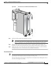
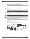
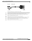
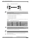
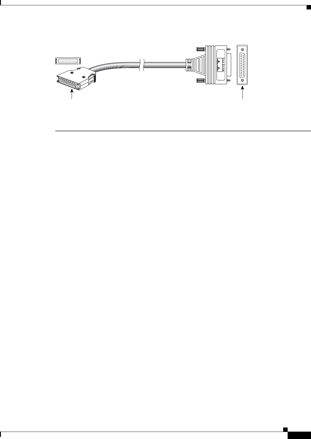
Figure 5-46 Fan Power Cable
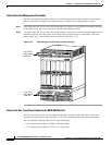
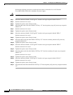
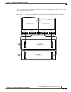
Complete the following steps to connect the fan power cabling:
Step 1 Insert the male connector of the upper fan tray power cable (46-inch) into the connector receptacle
(labeled F1) located at the bottom of the card cage, and push the connector in to seat it.
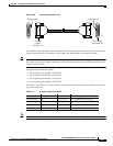
Step 2 Insert the connector at the other end of the cable into the upper fan tray receptacle as shown in
Figure 5-47, and push the connector in to seat it.
Step 3 Tighten the captive screws on the connectors. Do not use a power tool.
Step 4 Insert the male connector of the lower fan tray power cable (12-inch) into the connector receptacle
(labeled F2) located at the bottom of the card cage, and push the connector in to secure it.
Step 5 Insert the connector at the other end of the cable into the lower fan tray receptacle as shown in
Figure 5-47, and push the connector in to secure it.
Step 6 Tighten the captive screws on the connector. Do not use a power tool.
43983
To card cage To fan tray