


1-19
Cisco MGX 8800/8900 Series Hardware Installation Guide
Releases 2 - 5.2, Part Number OL-4545-01, Rev. H0, May 2006
Chapter 1 Product Overviews
Cisco MGX 8850 and MGX 8850/B Switches
MGX 8850 and MGX 8850/B Card Compartment
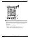
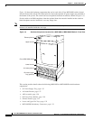
The MGX 8850 and MGX 8850/B switches each have 32 single-height slots in a compartment card cage
that holds cards and modules. Some single-height slots can be converted to double-height slots by
removing the service module slot dividers.
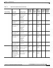
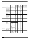
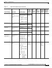
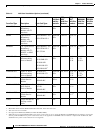
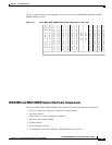
Table 1-3 lists the cards supported in a MGX 8850 and MGX 8850/B switches. Abbreviated card names
are listed in the Glossary. (The initial R- on some back cards means that this is a redundant back card,
which is used for 1:N card set redundancy without bulk distribution.)
Each slot on the front of the switch is numbered and has a corresponding slot located on the back of the
switch. There are 32 front card slots and 32 back card slots. Slots 1 through 16 are in the top bay, and
slots 17 through 32 are in the bottom bay of the switch.
Slot assignments and module support varies with the type of processor switching module you install in
your switch (PXM1E or PXM45). The processor switching module allows service providers to deploy a
complete set of services with up to 45 Gbps of nonblocking switching for low-density or remote
deployments.
The following sections describe the supported cards and slot assignments for each type of processor
switching module:
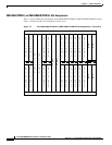
• MGX 8850 (PXM1E) and MGX 8850/B (PXM1E) Slot Assignments, page 1-20
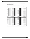
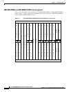
• MGX 8850 (PXM45) and MGX 8850/B (PXM45) Slot Assignments, page 1-22