


2-87
Cisco MGX 8800/8900 Series Hardware Installation Guide
Releases 2 - 5.2, Part Number OL-4545-01, Rev. H0, May 2006
Chapter 2 Illustrated Card List for MGX Switches and the MGX 8880 Media Gateway
Front Cards
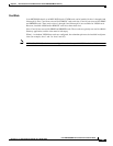
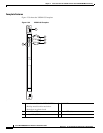
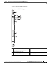
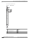
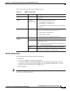
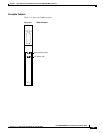
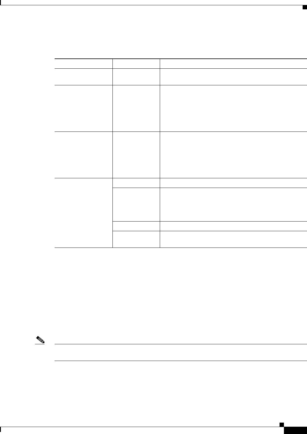
Table 2-36 describes the LEDs on the VXSM front cards.
Module Configurations
The VXSM supports the following module configurations:
• Standalone.
• 1:N card set redundancy, without bulk distribution
• 1:N card set redundancy, with bulk distribution—For line redundancy to be supported in this
configuration, there must be redundant PXM45 cards and redundant SRME/B cards. The APS
connector must be installed between the SRME cards.
• Bulk distribution.
Note For module configuration information, refer to Chapter 4, “Planning for Card Redundancy, Line
Redundancy, and Bulk Distribution”.
Table 2-36 VXSM Front Card LEDs
LED Status Description
ACT Green The VXSM card set (front card and back card) is in the
active state.
STBY Yellow or
blinking yellow
One of the following conditions exists:
• The VXSM is in Standby mode.
• The VXSM is in mismatch state.
• The VXSM DSPs are currently involved in the bootup
process.
FAIL Red When this LED is solid red and the ACT and STBY LEDs
are off, one of the following conditions exists:
• The module is in Reset mode.
• The module has failed.
• The card set is not complete (no back card).
PORT 1 through
PORT 24
Green The port is active with no alarms detected.
Red The port is active and a local alarm has been detected
(LOS, LOF, or AIS).
Note LOS is loss of signal; LOF is loss of frame; AIS is
alarm indication signal.
Yellow The port is active and a remote alarm has been detected.
Off The port is not configured, or the card set is configured as
a redundant card set and is in Standby mode.