


3-16
Cisco MGX 8800/8900 Series Hardware Installation Guide
Releases 2 - 5.2, Part Number OL-4545-01, Rev. H0, May 2006
Chapter 3 Preparing for Installation
Site Requirements for the MGX 8850 or MGX 8850/B Switch
Enclosed racks must have adequate ventilation. Ensure that the rack is not overly congested, because
each unit generates heat. An enclosed rack should have louvered sides and a fan to provide cooling air.
The enclosure must also provide adequate cooling through the use of an appropriately sized heat
exchanger or air conditioner, which dissipates the heat generated by existing remote terminal system
components and by the installed switch.
Ventilation
The following practices ensure proper ventilation for the MGX 8850 or MGX 8850/B switch:
• Install two fan trays within the switch: an upper and a lower fan tray
• Install an air intake plenum and an exhaust plenum within the switch
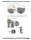
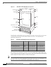
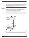
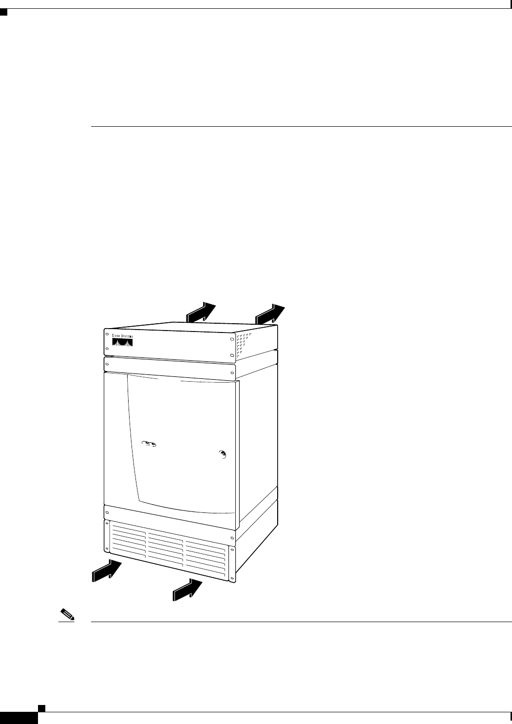
The main air intake vents are located in the air intake plenum component, which is installed under the
switch. The air intake vent for the AC power supply tray is located on the front of the power supply tray
panel. All air exhaust vents are located at the rear of the exhaust plenum component. Ensure that the
intake and exhaust vents are not obstructed in any way. Figure 3-4 shows the air flow through the switch.
Figure 3-4 Air Flow Through Intake and Exhaust Vents for the MGX 8850 or MGX 8850/B Switch
Note Electrical equipment generates heat. Ambient air temperature might not be able to cool equipment to
acceptable operating temperatures without adequate circulation. Ensure that the room in which you
operate your system has adequate air circulation.
84461