


3-25
Cisco MGX 8800/8900 Series Hardware Installation Guide
Releases 2 - 5.2, Part Number OL-4545-01, Rev. H0, May 2006
Chapter 3 Preparing for Installation
Site Requirements for the MGX 8850 or MGX 8850/B Switch
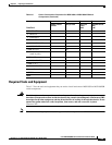
Required Tools and Equipment
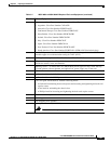
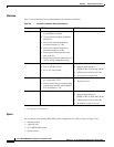
Table 3-7 lists the tools and equipment that you need to install and remove MGX 8850 or MGX 8850/B
switch components.
Warning
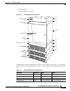
Blank faceplates and cover panels serve three important functions: they prevent exposure to
hazardous voltages and currents inside the chassis; they contain electromagnetic interference (EMI)
that might disrupt other equipment; and they direct the flow of cooling air through the chassis. Do not
operate the system unless all cards, faceplates, front covers, and rear covers are in place.
Statement 1029
Note For additional cabling requirements, see Appendix B, “Cable Specifications.”
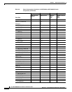
VISM-PR-8T1 60
• RJ48-8T1 3
• R-RJ48-8T1 3
VXSM-4-155 160
• VXSM-BC-4-155 8
• VXSM-R-BC 9
VXSM-48T1E1 110
• VXSM-BC-24T1E1
(used in pairs)
9
VXSM-6-T3 154
• VXSM-BC-3T3 6.3
VXSM-3-3T3
• VXSM-BC-3T3
Fan tray (for each) 75.6
DC PEM 20
Totals
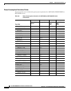
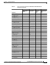
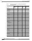
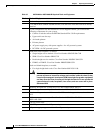
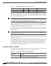
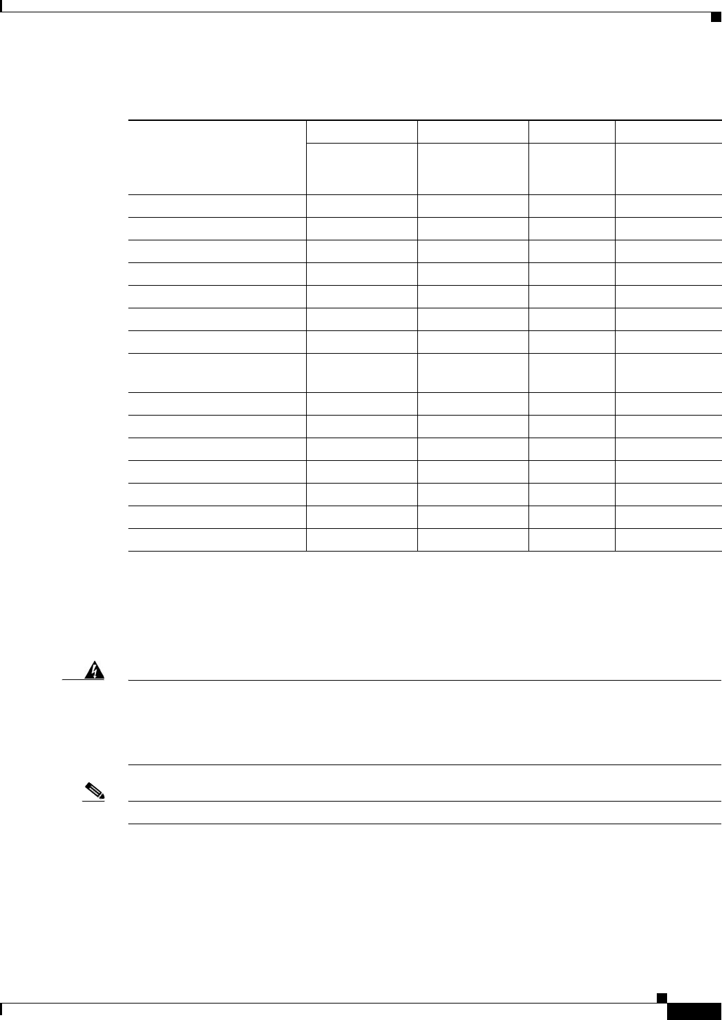
Table 3-6 Power Consumption Calculation for MGX 8850 or MGX 8850/B Switch
Components (continued)
Front Card
ABCD
Number of Cards
Installed
Watts per Card Total Card
Power
(AxB)
Total 48-V Current
(ADC)
(C/48)