


B-6
Cisco MGX 8800/8900 Series Hardware Installation Guide
Releases 2 - 5.2, Part Number OL-4545-01, Rev. H0, May 2006
Appendix
Control and Clock Cabling
The PXM-UI-S3 or PXM-UI-S3/B cards go into slots 1 and 2 for the MGX 8830 and MGX 8830/B
switches.
For redundancy where one user interface back card is present, connect to both ports, using EXT CLK1
as the primary source and EXT CLK2 as the secondary source.
For redundant PXM configurations where two user interface back cards are present, use a Y-cable to
connect to the EXT CLK1 input of Slot 7 and the EXT CLK1 input of Slot 8. For BITS source protection,
connect another Y-cable to the EXT CLK2 input of Slot 7 and the EXT CLK2 input of Slot 8. (For
MGX 8830 switches, these cards would be in slots 1 and 2.)
Cable Specifications for Y-Cables and Cable Adapters for Clocking
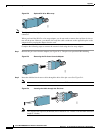
There are two types of Y-cables for clocking:
• One type has an RJ-45 plug at the single end, and RJ-45 connectors at the Y ends
• One type has a BNC coax connector at the single end, and RJ-45 connectors at the Y ends
Note In systems with redundant PXM cards and an external clock source, the single external clock source
should be connected to both PXM-UI-S3 cards using a short Y-cable.
A wire-wrap adapter can be used for clocking. See “Connect the External Clock Using a Wire-Wrap
Adapter” section on page B-7.
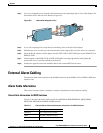
A cable adaptor with an RJ-45 connector on one end and a BNC coax connector at the other end can be
used for clocking.
The maximum cable length is 533 feet (162.46 m) between the MGX switch and the first repeater or
channel service unit (CSU). Selection of cable length equalizers is used. Wire build-out is required.
T1/E1 Clock Input Cable Information
The T1 RJ-48 clock port can accept either a T1 or an E1 Building Integrated Timing Supply/Synchronous
Equipment Timing Source (BITS/SETS) clock input signal. The E1 RJ-45 clock port can accept twisted
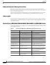
pair or 75-ohm coaxial cable. See Table B-5 for cable and signal information for the external clock.
Building Integrated Timing Supply (BITS) Clock Connector Pin Assignments
For MGX 8850 (PXM1E/PXM45), MGX 8850/B, MGX 8950 switches, and the MGX 8880 Media
Gateway, the RJ-48 BITS clock connector has a 100-ohm termination for T1 and a 120-ohm termination
for E1.
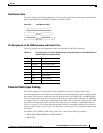
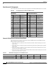
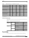
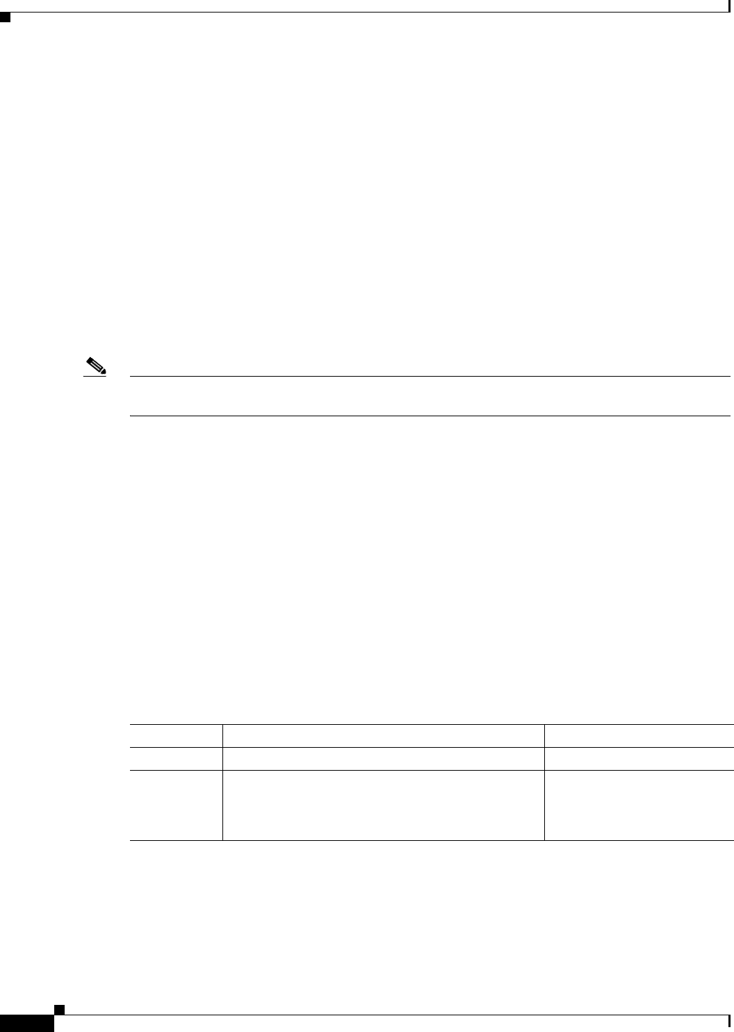
Table B-5 Cable and Signal Information for the External Clock Ports on the PXM-UI-S3 or
PXM-UI-S3B Card
Carrier Cable Media Signal Type (Data or Sync)
T1 22 AWG, twisted pair with shield. 100-ohm Data
E1 22 AWG, twisted pair with shield. 120-ohm, bipolar
or
75-ohm coaxial cable
Data