


5-58
Cisco MGX 8800/8900 Series Hardware Installation Guide
Releases 2 - 5.2, Part Number OL-4545-01, Rev. H0, May 2006
Chapter 5 Installing the Cisco MGX Switch or Gateway
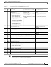
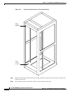
Installing the MGX 8950 Switch
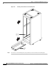
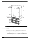
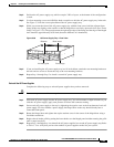
Figure 5-35 Component Locations in a MGX 8950 System
Note If you plan to expand your system to include more switches in the future, allow space in the rack for
additions, keeping in mind the weight distribution and stability of the rack.
Prepare for Rack Installation
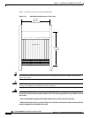
The minimum distance between left and right mounting rails (as you face the rack) must be 17.75 inches
or 45.08 cm. (Some 19-inch racks have only 17.50 inches between the rails.) The width of the
components, such as the card cage and fan tray, is 17.72 inches.
When installing a MGX 8950 system in a 19-inch rack, adhere to the following guidelines:
• Open-rack configuration—The switch and hardware components (optional AC power supply tray,
air intake plenum, upper and lower fan trays, and exhaust plenum) need to be mid-mounted in the
rack. Brackets for that purpose are included with the system.
43977
A
C
D
C
1200W
A
C
D
C
1
2
0
0
W
A
C
D
C
1200W
A
C
D
C
1200W
A
C
D
C
1200W
AC
D
C
1200W
AC
DC
1
2
0
0
W
A
C
D
C
1
2
0
0
W
Exhaust plenum
3.5 in.
2 RU
1 RU
10 RU
1 RU
3 RU
3 RU
3 RU
Upper fan tray
1.75 in.
Lower fan tray. 1.75 in.
Card cage
17.5 in.
Air intake plenum
5.25 in.
Optional
AC power tray
5.25 in
Optional
AC power tray
5.25 in
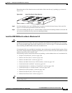
Status LEDs