


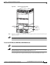
5-35
Cisco MGX 8800/8900 Series Hardware Installation Guide
Releases 2 - 5.2, Part Number OL-4545-01, Rev. H0, May 2006
Chapter 5 Installing the Cisco MGX Switch or Gateway
Installing the MGX 8850 (PXM1E/PXM45) Switch, MGX 8850/B or MGX 8880 Media Gateway
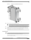
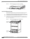
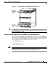
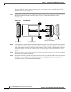
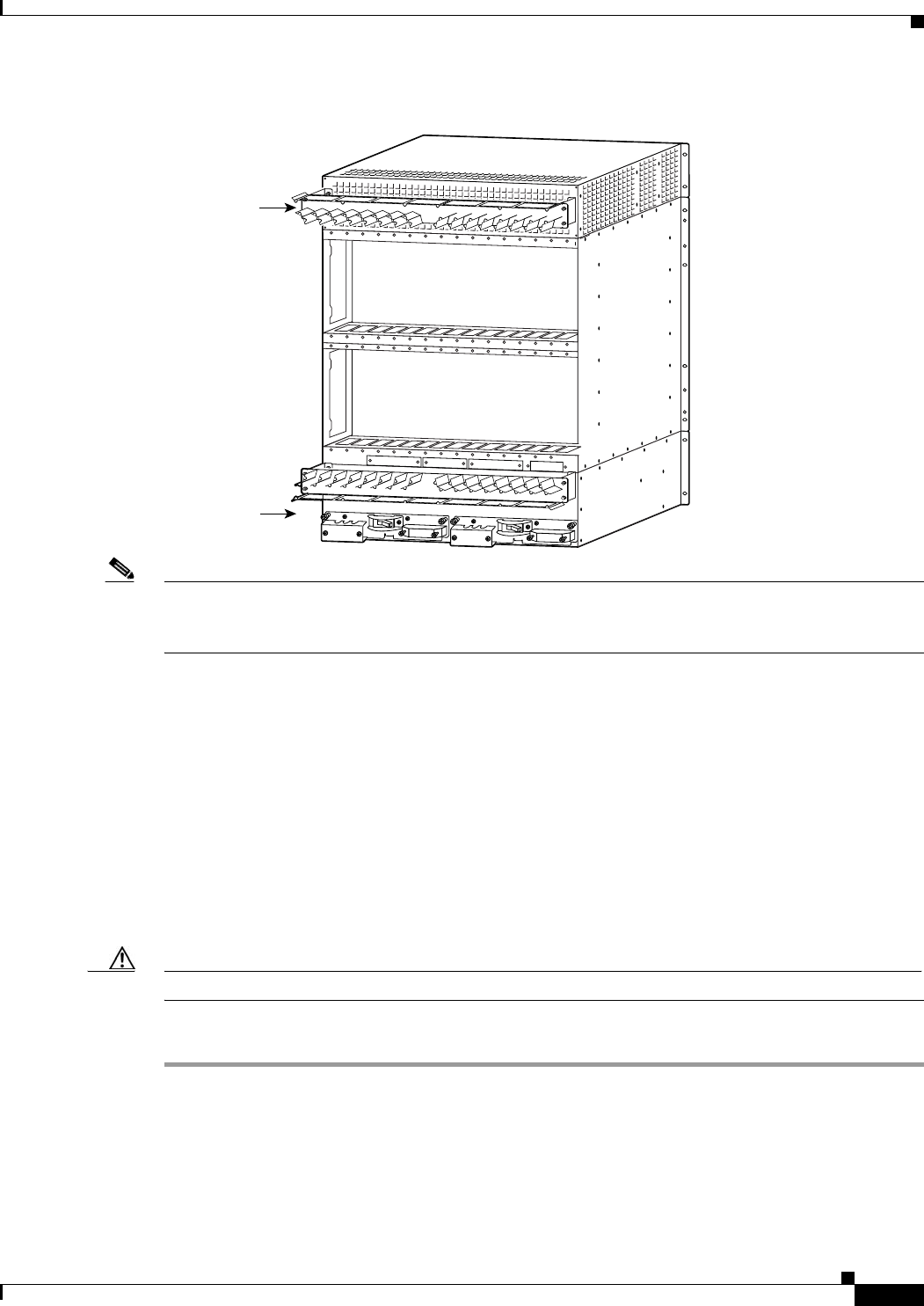
Figure 5-18 Cable Management Assembly at Back of an MGX 8880 System
Note On an MGX 8880, you might find that some cables do not fit into the cable management system. If the
cables are too thick (for example, the T1E1 cards have thick cables), remove the fins, which are attached
with two small Phillips-head screws.
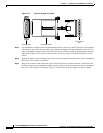
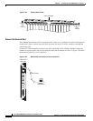
Connect the Fan Tray Power Cables to the Cisco MGX 8850 or MGX 8850/B Switch
The fan trays receive power from the backplane through fan tray power cables. To reach the backplane
D-connector, the fan power cable D-connector passes through an opening at the bottom rear of the card
cage. There are four openings for cabling: two for system power and two for fan tray power. From left
to right, the sequence of the access openings in the card cage is as follows:
1. System power (source A)
2. Fan tray power (lower fan tray)
3. System power (source B)
4. Fan tray power (upper fan tray)
Caution Do not use a power screwdriver on captive screws.
Complete the following steps to connect the fan tray power cables to the switch:
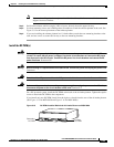
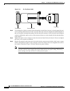
Step 1 Notice that the smaller side of the backplane D-connector faces down, and position the smaller side of
the cable D-connector so that it also faces down. Figure 5-19 shows the connectors for the fan tray
power cable.
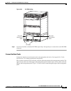
116513
Upper cable
management
assembly
Lower cable
management
assembly