


3-32
Cisco MGX 8800/8900 Series Hardware Installation Guide
Releases 2 - 5.2, Part Number OL-4545-01, Rev. H0, May 2006
Chapter 3 Preparing for Installation
Site Requirements for the MGX 8950 Switch
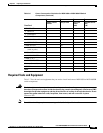
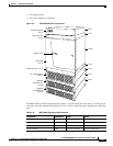
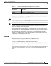
Plan so that the rack accommodates your needs. An AC-powered MGX 8950 switch occupies 35.00
inches (88.9 cm or 20 RUs) of vertical space. A DC-powered MGX 8950 switch occupies 29.75 inches
(75.69 cm or 17 RUs) of vertical space.
Note In a central office (CO) and private enterprise (PE) environment, the total amount of rack space should
not exceed 42 RUs. If your total configuration exceeds 42 RUs, either replan your configuration or use
more than one rack to house the Cisco MGX 8950 switch components.
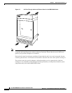
The location of the Cisco MGX switch and the layout of your rack or wiring room are extremely
important for proper system operation. If equipment items are too close together, ventilation might be
inadequate, and panels might become inaccessible. As a result, the system might malfunction or even
shut down, and maintenance and repair are made more difficult.
A Cisco MGX switch requires access space around the cabinet. The suggested clearance at the front and
the back of the cabinet is 30 inches (76.20 cm). The suggested clearance on each side of the cabinet is
12 inches (30.48 cm).
Note A vertical gap of 0.047 to 0.077 inch (0.119 to 0.196 cm) or about 1/16 inch must exist between adjacent
modules to allow for module removal.
Position the switch should so that it does not interfere with the routing of cables and the termination of
telephone or carrier circuits. Raised flooring is recommended so that there is enough space under the
flooring for cables and wiring.
When planning your site layout and equipment locations, keep in mind the precautions that are described
in the “Safety Requirements” section on page 3-2 and the “Site Requirements for the MGX 8950 Switch”
section on page 3-28. These precautions can help you to avoid equipment failures and can reduce the
possibility of environmentally caused shutdowns. If you are currently experiencing shutdowns or
unusually high error rates with your existing equipment, these precautions might help you isolate the
cause of failures and prevent future problems.
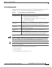
Temperature, Altitude, and Humidity
The system can tolerate a wide range of temperatures. Table 3-11 provides the Cisco recommendations
for temperature, altitude, and humidity conditions in a CO and PE environment.
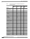
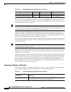
Air intake plenum 3 RUs 5.25 in. (13.34 cm) 21.5 in. (54.61 cm)
AC power supply tray (optional) 3 RUs 5.25 in. (13.34 cm) 21.5 in. (54.61 cm)
Table 3-10 MGX 8950 Rack Space Requirements (continued)
Component Rack Space Height Depth
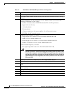
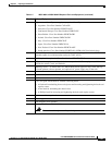
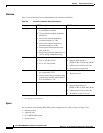
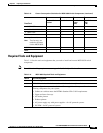
Table 3-11 CO and PE Operating Environment Requirements
Environmental
Specification Description
Temperature 32 to 104ºF (0 to 40ºC)—Normal operation
68 to 86ºF (20 to 30ºC)—Recommended operation
1