


B-19
Cisco MGX 8800/8900 Series Hardware Installation Guide
Releases 2 - 5.2, Part Number OL-4545-01, Rev. H0, May 2006
Appendix
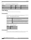
Frame Relay Cabling
E1 Cabling
E1 trunk cables connect the customer DSX-1 cross-connect point or E1 CSU to the MGX switch at the
FRSM E1 back card (SMB-8E1).
See Table B-22 for E1 trunk cable and connector information.
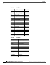
See Table B-21 for pin assignments for the RJ-48C T1 and E1 connector.
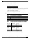
See Table B-23 for pin assignments for the RJ-48C E1 connector—unbalanced.
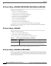
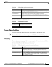
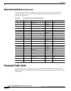
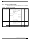
MGX-12IN1-S8 Back Card Cables
The back card for the MGX-FRSM-HS2/B is the MGX-12IN1-S8. Each port on the back card connects
through a DTE version or DCE version of the Cisco 12IN1 cable. The signal on the back card depends
on whether the back card connector is DTE or DCE and whether the back card has been set as X.21 or
V.35 as sh own in Table B-24.
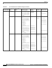
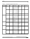
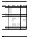
For the signals on the back card, see Table B-25 and Table B-26. The tables show the signal acronym,
signal name, and signal source.
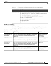
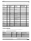
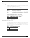
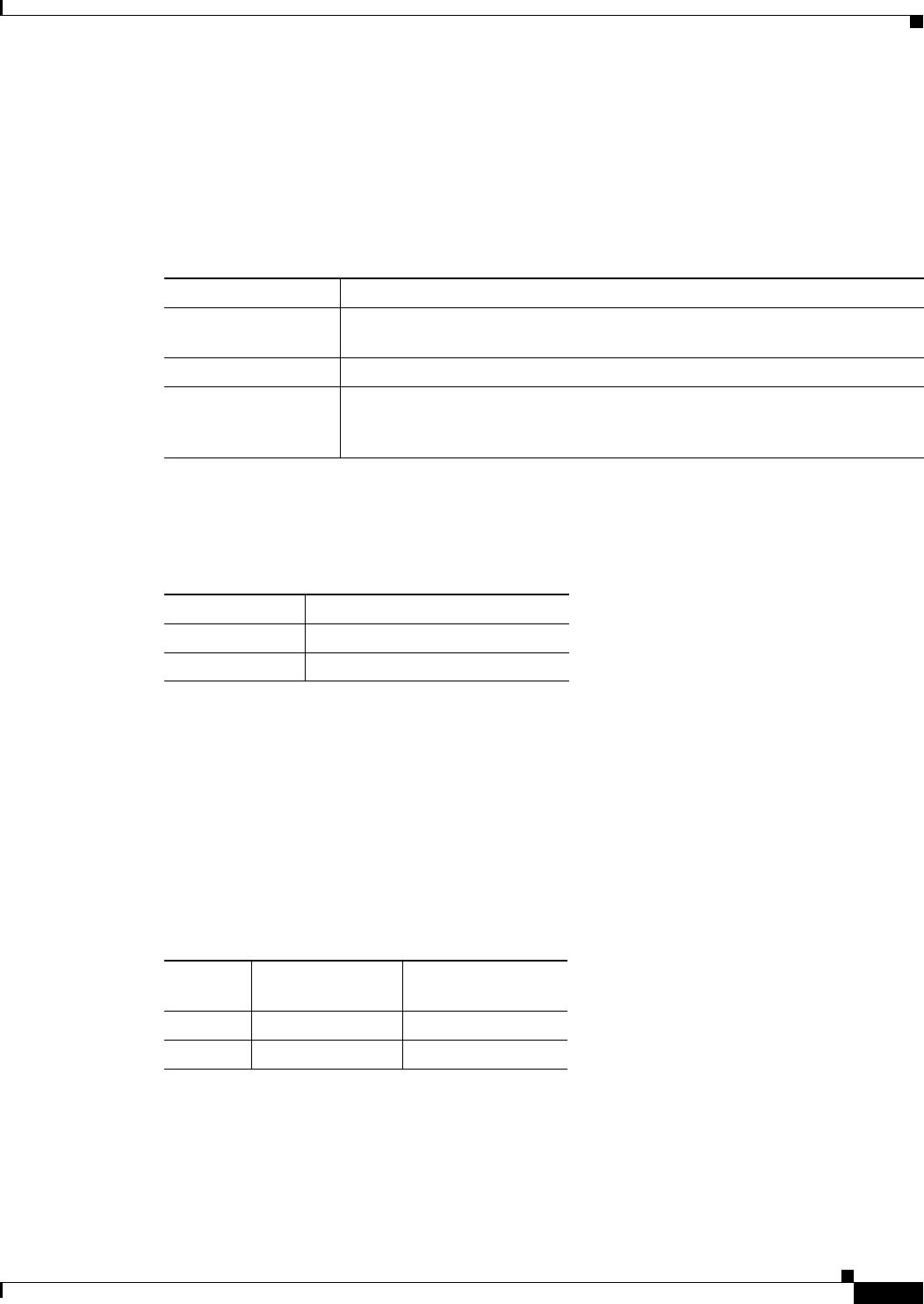
Table B-22 E1 Trunk/Circuit Line Cable and Connector Specification
Cable Parameter Description
Cable type
(BNC-8E1)
75-ohm coax cable for unbalanced connection. Two cables or pairs
(one transmit and one receive) per E1 line.
Cable connector 16 female SMB for unbalanced connection.
Maximum cable
length
Approximately 100 meters (328 feet) maximum between the Cisco MGX 8850
or Cisco MGX 8830 switch and the first repeater or CSU. A selection of cable
length equalizers is available.
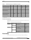
Table B-23 RJ-48C E1 Connector Pin Assignments—Unbalanced
Connector Description
Rx BNC Receive E1 from trunk
Tx BNC Transmit E1 to trunk
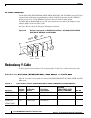
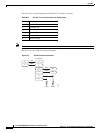
Table B-24 12IN1-S8 and 12IN1-S4 Back Card Cable Types
Cable
Type X.21 V.35
DCE X.21 DCE V.35 DCE
DTE X.21 DTE V.35 DTE